Overview
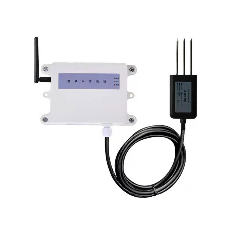
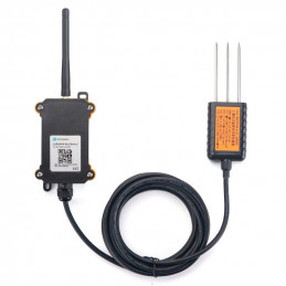
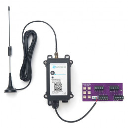
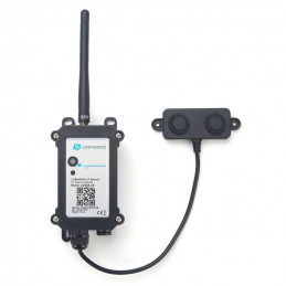
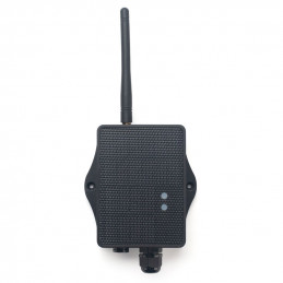
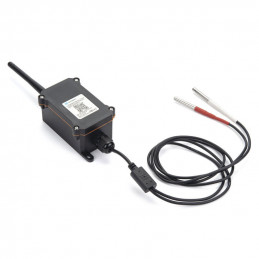
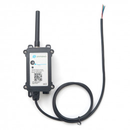
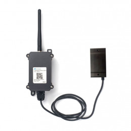
LT-W208 LoraWAN Soil NPK Sensor node is powered by battery, with long battery life, no wiring, and convenient construction. Compared with the traditional 470M modulation technology, LoraWAN spread spectrum technology takes into account communication distance, anti-interference, low power consumption, ensures longer communication distance, and has stronger penetration ability (commonly known as the king of wall penetration, which can penetrate 5~12 floors). Suitable for applications with obstacles. Products are widely used in the field of smart.
Main technical indicators
|
Power supply
|
1 pc 3.6V lithium battery
|
|
working
environment
|
-20~50 ℃, 15~90%RH (no condensation)
|
|
Range
|
N
|
0~1999mg/kg
|
|
P
|
0~1999mg/kg
|
|
K
|
0~1999mg/kg
|
|
Working frequency
|
915-930MHz
|
|
Network access
|
OTAA.ABP
|
|
Networking method
|
Follow LoraWAN protocol stack
|
Installation and commissioning
3.1 DIP switch setting (it has been set at the factory, see the product nameplate for details, if you need to modify it, follow the instructions below)
3.2.1 The first one from the left picture: 1, 2, 3, and 4 are the value of the upload cycle dial code * 5 minutes.
3.2.2. The second sensor address from the left figure is selected by the DIP switch. The user needs to select and set the slave address within 001~255. After the setting is completed, power off and restart are valid. The method of setting the address by the DIP switch is as follows: The picture shows the DIP switch and the value represented by each bit. Dial to "ON" is a valid value, and to the opposite direction of "ON" is an invalid value. The address is the value obtained by adding the valid values. Example: If the address is 100, then dial switch 3, 6, and 7 to ON position, that is, 4+32+64=100.
The sensor register location is as follows:
|
Register address
|
000AH
|
000BH
|
000CH
|
|
Parameters
|
N
|
P
|
K
|
|
Unit
|
mg/kg
|
mg/kg
|
mg/kg
|
|
Range
|
0-1999
|
0-1999
|
0-1999
|
|
Sample value
|
/1
|
/1
|
/1
|
When the sensor is powered on, make sure that the gateway is powered on. Only the sensor is powered on for a long time, and the gateway is not powered on, which will reduce the service life of the sensor.
Protocol analysis:
Active data upload example: 03 03 1C 00 00 00 00 00 00 00 00 00 00 00 00 00 00 00 00 00 00 00 00 00 10 00 A0 00 01 0C 83 F9 DD 03
Sensor address; 03
function code; 1C
Data length; 00 00
blank 00 00 blank 00 00 blank 00 00 blank 00 00 blank 00 00 blank 00 00 blank 00 00 blank 00 00 blank 00 00 blank 00
10 N data 16mg/kg 00 A0
P data160mg/kg 00 01
K data 1mg/kg 0C 83
battery voltage F9 DD verify
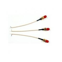
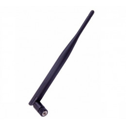
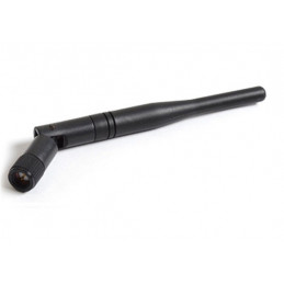
Connect the antenna, first time using it, If it has been powered on, it can be used directly; if it is not powered on, insert the battery and insert the 2-pin plug of the battery box into the battery socket (white) of the circuit board. Wait for a while for the power indicator to stay on, indicating that the program is running. If you need to reset the DIP switch, please turn off the power first (more than 1 minute to ensure that the microcontroller is completely reset) and then power on again. At this time, the user can install the sensor on site and put it into use. The wireless sensor needs to be used together with our wireless receiving gateway. After receiving the wireless measuring point signal, the wireless receiving gateway converts it into network data or 485 serial port data, and then can be transmitted to the monitoring software platform. For the use of the wireless gateway, please refer to the instruction manual of the wireless gateway. The on-site installation of the wireless sensor should be placed as high as possible and in a relatively open place. It is recommended to be more than 1 meter away from the ground; avoid placing metal objects around the sensor to prevent the wireless signal from being shielded and weakened; electronic interference will come from the following Objects, so they should be avoided: generators, high-current equipment, high-voltage relays, transformers, etc.; vibration or shock may also become a source of interference, so the equipment should be as static as possible when installing the equipment. Do not install the device in an environment beyond the measurement range of the sensor, otherwise the product will not work properly and the sensor will be permanently damaged.
Attention
※When the battery voltage is too low, please replace the battery in time, otherwise the consequences due to internal leakage of the battery fluid will not be covered by the warranty. 3.6V lithium battery voltage is not lower than 2.8V.
※ The sensor station address setting must not be duplicated with other slave station addresses.
※ If the sensor is faulty and needs to be replaced, it is only necessary to set the new sensor node address and channel address to be the same as the original sensor, and it can be put into use after power-on. ※ The communication distance in this manual refers to the visible distance in the open field, and the antenna is more than 3 meters away from the ground. The actual distance should be reduced according to the site environment.
※ When the product leaves the factory, the wireless communication is in the mode of timed acquisition and active upload.
※ The battery life is calculated by our company with reference to the capacity of "Nanfu" alkaline battery (or domestic brand 3.6V lithium battery) and the default collection cycle. In order to facilitate users to grasp the battery life cycle, it is strongly recommended that users choose Nanfu and other well-known brands battery or lithium battery. When the sensor is in a high temperature and high humidity environment for a long time, the battery life will be greatly reduced, please prepare in advance according to the site environment.
※ Our company also produces Lora wireless acquisition terminal (router), wireless control terminal (router), and LORA/GPRS gateway, LORA/serial gateway, LORA/WIFI gateway, etc., which are very convenient for LORA wireless sensors to be used together.
Common problems and solutions Possible reasons why the information collected by the sensor cannot be read successfully
1、If the device address is wrong, or there are devices with duplicate addresses, check whether the sensor address is set correctly, and use a multimeter to measure the status of the DIP switch if necessary.
2、Wireless sensors should not be placed in an environment surrounded by metal obstructions, such as a room with metal walls.
3、The distance between the wireless sensor and the wireless gateway should be more than 5 meters. For example, the external antennas of the sensor and the gateway need to be removed during indoor short-range testing
DECODE Example:
function Decode(fPort, bytes, variables) {
var paramLength = bytes[2]/2;
var params = new Object();
for(var i=0;i<paramLength;i++)
{
params["param"+i] = bytes[3+i*2]*256+bytes[4+i*2];
}
return params;
}
DECODER
function Decode(fPort, bytes, variables) {
var paramLength = bytes[2]/2;
var params = new Object();
params["N"] = bytes[23]*256+bytes[24];
params["P"] = bytes[25]*256+bytes[26];
params["K"] = bytes[27]*256+bytes[28];
params["BAT"] = bytes[29]*256+bytes[30];
return params;
}
Useful Link:
LT-W208 LoraWAN Soil NPK Sensor node Connect to Dragino gateway and ChirpStack
