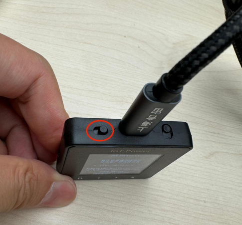
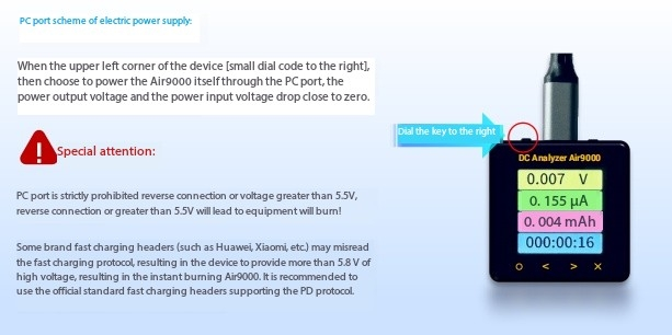
The small dial switch is switched to the right side which is powered by USB by default:
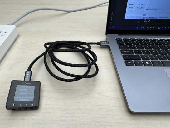
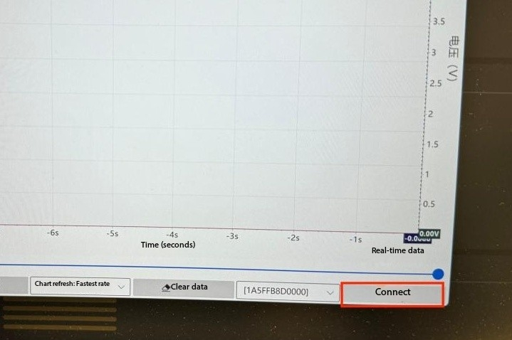
Click the “Connect” button in the lower right corner of the PC tool to connect the DWM-Air9000
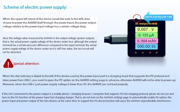
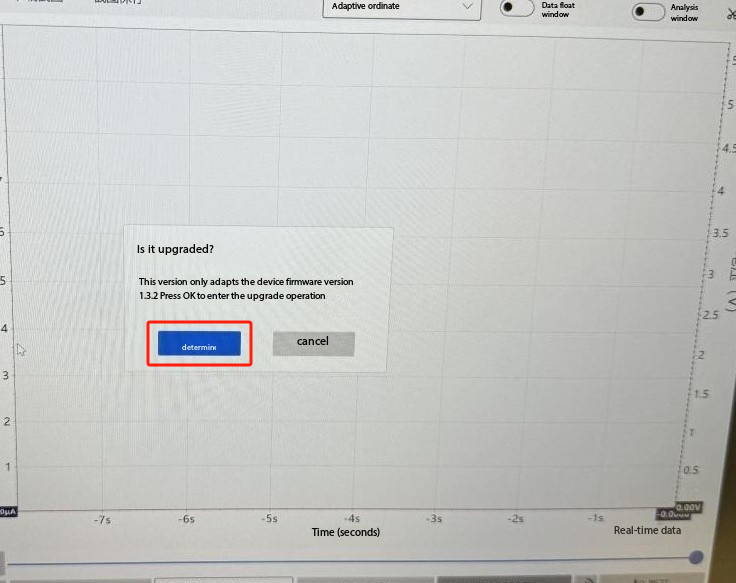
The first connection to the PC Tool opportunity prompts you to upgrade the DWM-Air9000 latest firmware, and click “OK” After the software is successfully upgraded, you need to click “Connect” again.
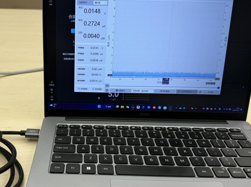
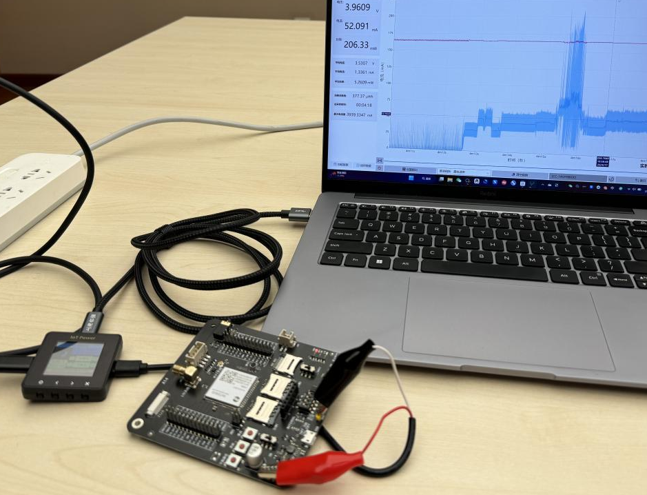
After successfully connecting to the DWM-Air9000, the PC tool displays the circuit ripple random value.
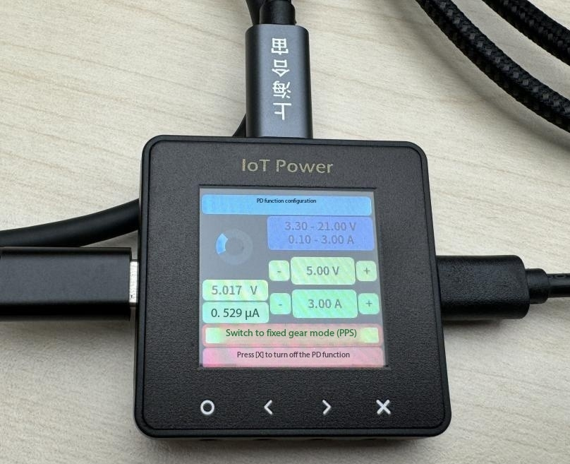
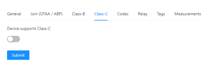
DWM-Air9000 Turn to the PD function page, you can see that the PD / PPS function has been opened by default, which is the premise of adjusting the voltage output value of the charging head;
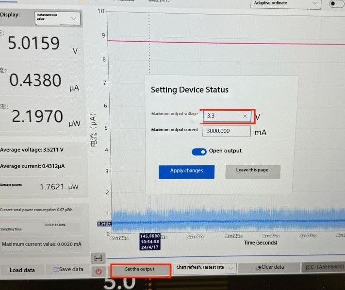
The default voltage output value of the charging head is 5V, You can reset the output value to 3.3V as follows example:
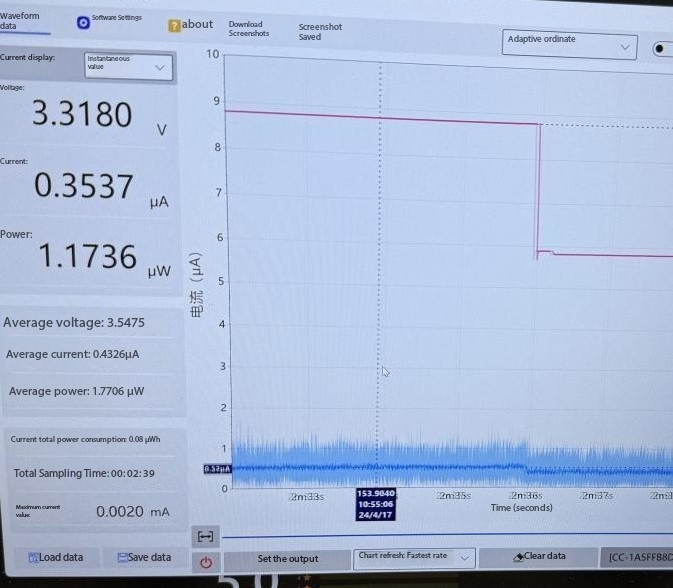
After resetting done you can see below shows:
Now you are ready to test your device here is an example:
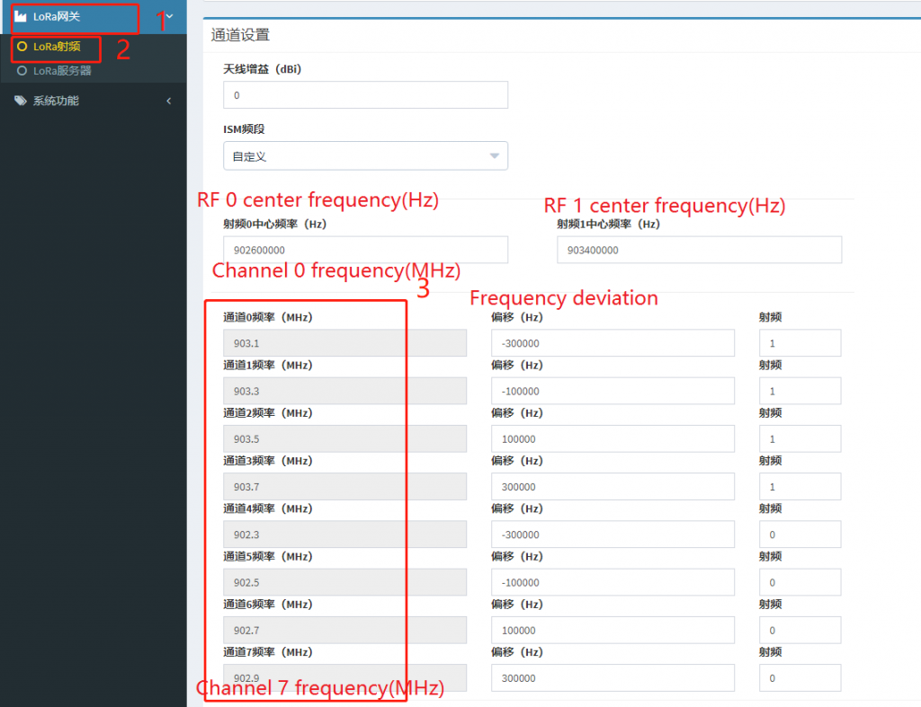
Log in to the web management page of the gateway and configure the LoRa radio as shown in the figure below. The figure below shows the configuration of U915 as an example.
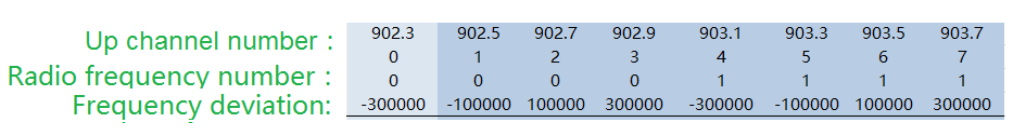
The default working frequency of the Smoke Sensor is 0 to 7 channels in the US915 band, and the corresponding frequency points are shown in the following figure.
Click “LoRa Gateway” and “LoRa RF” in the left menu bar, and set according to the working frequency of the LoRa smoke sensor. RF 0 center frequency: 902.6MHz, RF 1 center frequency: 903.4MHz, The corresponding frequency points are 902.3, 902.5, 902.7, 902.9, 903.1, 903.3, 903.5, 903.7 (Unit: MHz)
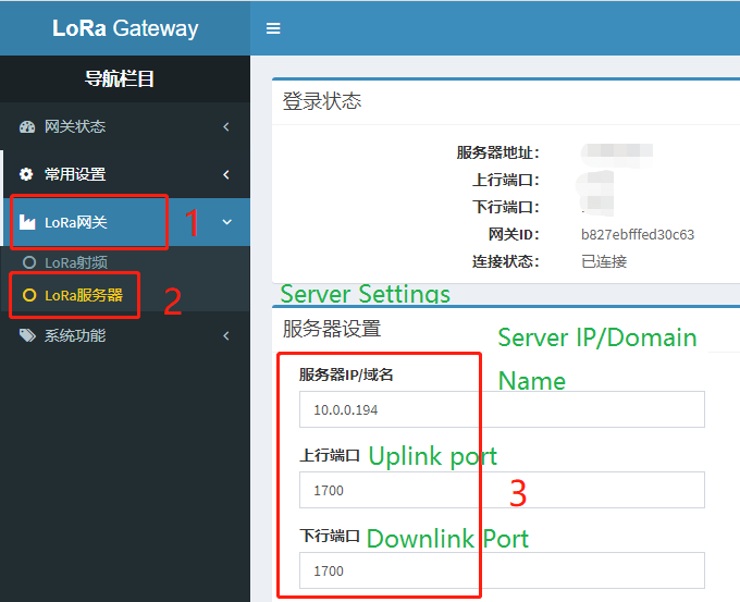
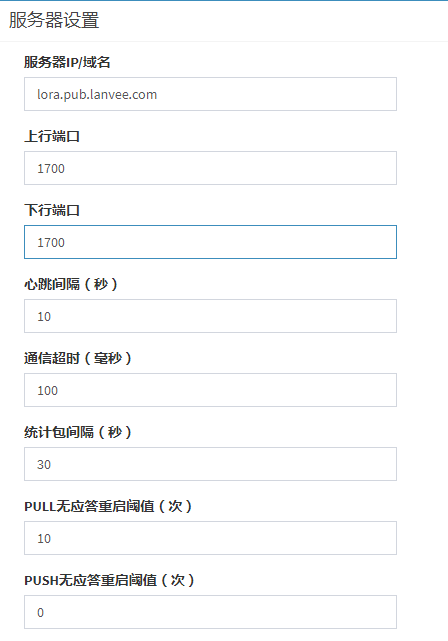
LoRa Gateway Server Setting
Configure the LoRa server
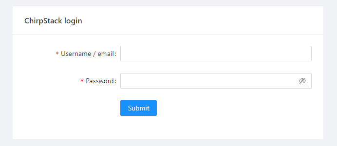
1. Login to ChirpStack
In the browser address bar, enter the ChirpStack server address, then enter your account and password to log in.
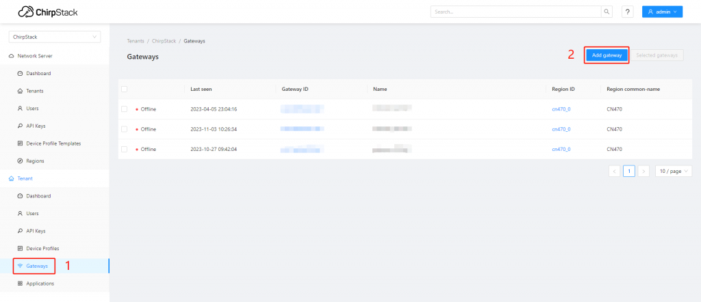
2. Add Gateway
Go to “Gateways”, click “Add gateway” in the top right corner to add a gateway.
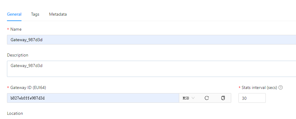
You have to make sure a LoRawan Gateway and the sensor node are ready for data transmission if you want to check the data receiving through the Chripstack.Name: Custom gateway name; Description: Gateway description; Gateway ID: Enter the gateway EUI, fill in according to the actual situation; Stats interval: The interval at which the gateway sends statistics, unit: s;
Fill in the required gateway information to be added, then click “Submit”.
3. Gateway configuration
Log in to the gateway’s configuration page, fill in the actual ChirpStack server address and uplink/downlink ports according to the actual information of the ChirpStack server.
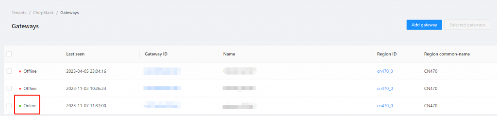
3.1 Gateway status
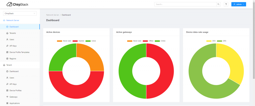
Go to the “Gateway” interface, in the gateway list, you can view the gateway connection status, Online indicates the gateway has successfully connected.
3.2 Add Device
Using a smoke sensor device as an example. For other devices, modify according to the actual parameters:
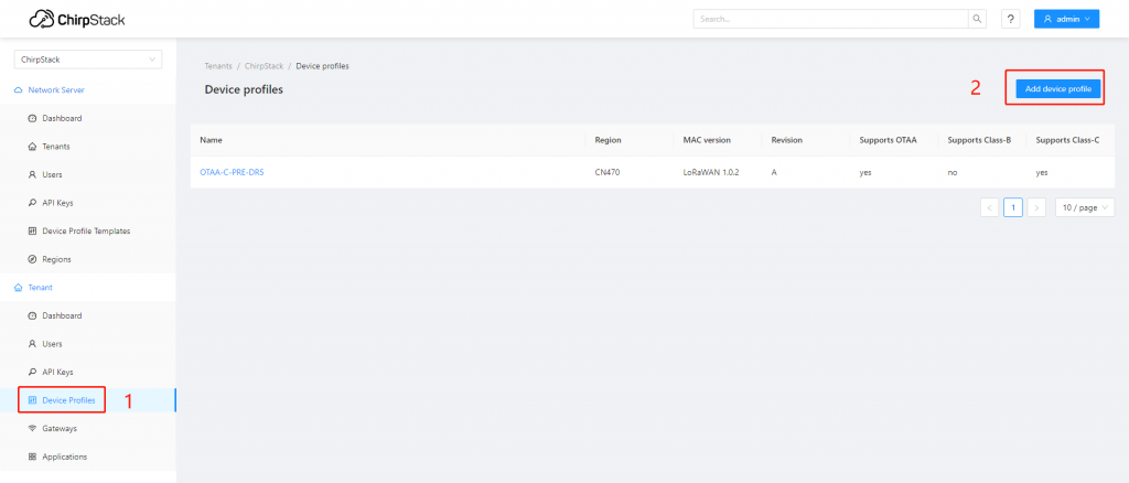
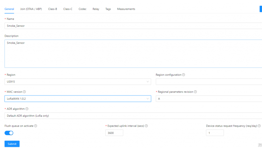
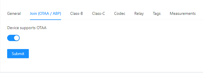
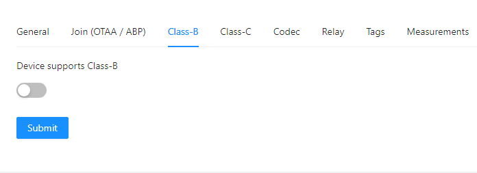
3.2.1 Create device profile
Go to “Device Profiles”, click “Add device profile” in the top right corner to add a device profile.
Each command supports at least one type. Format description:
1. The command starts with “at+” and ends with<CR>(carriage return, hexadecimal value is 0x0D, which is represented by ‘ r’ in C language); 2. If the end of the command (or in the command) contains a newline character (<LF>),<LF>is ignored; 3.<>: indicates the part that must be included; 4. []: indicates an optional part; 5. Commands and parameters are not case sensitive.
The return format of command execution varies depending on the command, and there are mainly the following types of formats:
1. <ok><CR><LF>, indicating success, more common in the return of configuration commands; 2. <error,1><CR><LF>, indicating that the input command cannot be recognized; 3. <error,2><CR><LF>, indicating that the command can be recognized, but the input parameter is invalid, which is more common in the return of configuration commands; 4. <parameter1>[,<parameter2>,…<parametern>]<CR><LF>, which is more common in the return of query commands; 5. Other forms, which vary from command to command, are more common in the return of execution-type commands. Where <CR> is the carriage return character and <LF> is the line feed character (0x0A in hexadecimal, represented by ‘\n’ in C language).
1.3 Command Reply
1.3.1 Success
After executing the command, if the return is successful, return ok\r\n.
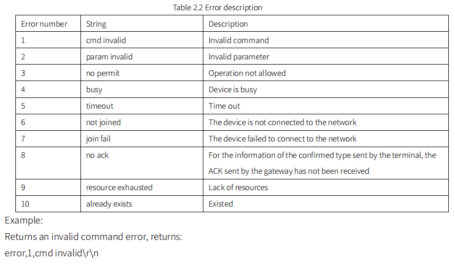
1.3.2 Error
After executing the command, if an error is returned, it has the following format: error,<error number>,[error description string]\r\n Among them, the error number and error description string are shown in the following table:
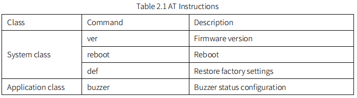
1.4 System Commands
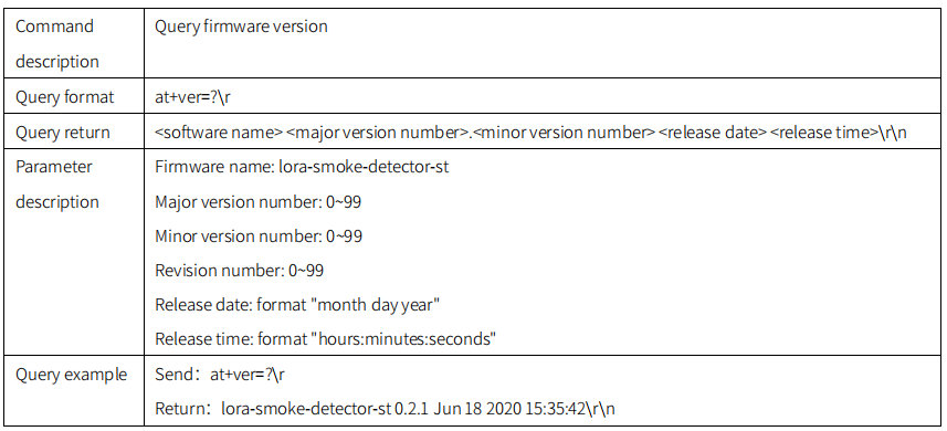
1.4.1 ver
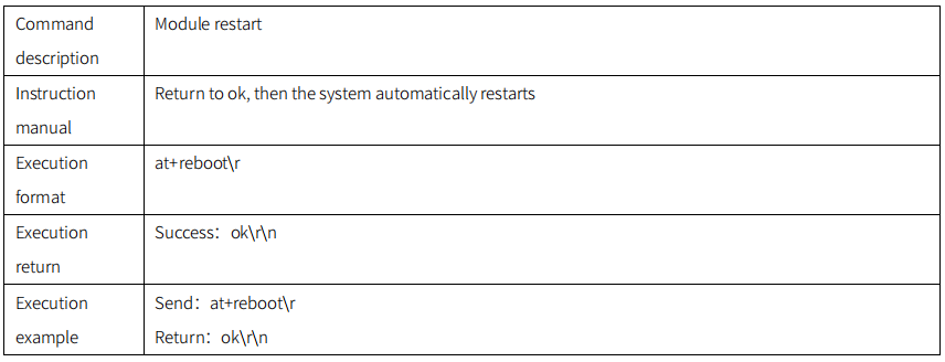
1.4.2 reboot
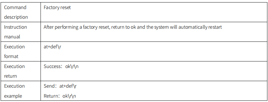
1.4.3 def
1.5 Application Commands
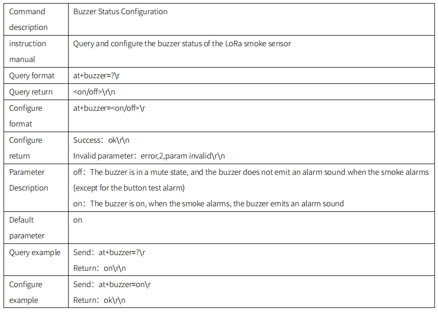
1.5.1 buzzer
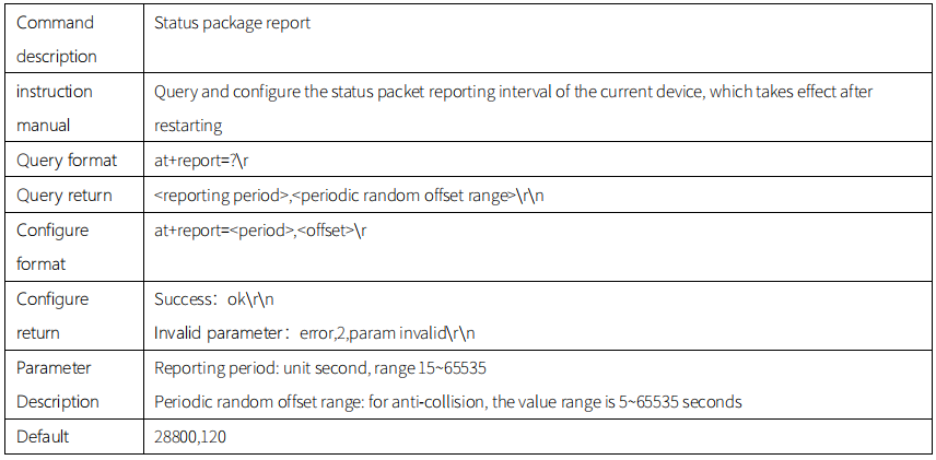
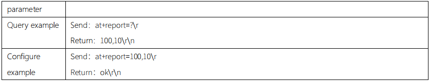
1.5.2 report
Communication Protocol
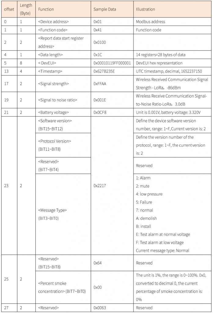
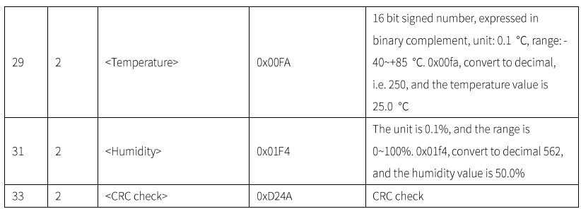
1.1 Periodic reporting
The status reporting period defaults to 8h/packet :
Report example :01 41 01 00 1C 00 01 01 19 FF 00 00 01 62 7B 23 5E FF AA 00 1E 01 4C 22 17 64 00 00 63 00 FA 01 F4 D2 4A Data Analysis: Device DevEUI: 00010119FF000001; UTC Timestamp: 1652237150; Signal Strength: -86dBm; Signal-to-Noise Ratio: 3.0dB; Battery Voltage: 3.32V; Software Version: 2, Protocol Version: 2; Message Type: Normal; Smoke Concentration Percentage: 0%; Temperature: 25.0℃; Humidity: 50.0%; CRC Check: 0xd24a
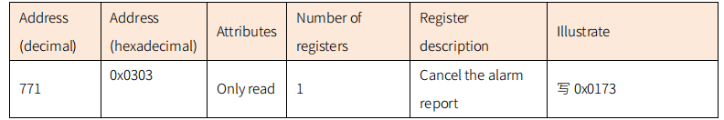
1.2 Cancel the alarm report
When the device detects that the smoke concentration is 100%, the device will trigger an alarm and report at a high frequency of 10s/packet. Users can cancel the smoke alarm through the following ModBus commands. Disarm the alarm report and only stop the high-frequency report of 10s/packet .
The device follows the standard ModBus communication protocol, please use the 0x10 function code to write to the register. Example of Canceling the alarm report: 01 10 03 03 00 01 02 01 73 d5 16
Device Debugging
1.3 LoRaWAN NS
The following LoRaWAN NS operations only show the general operation process
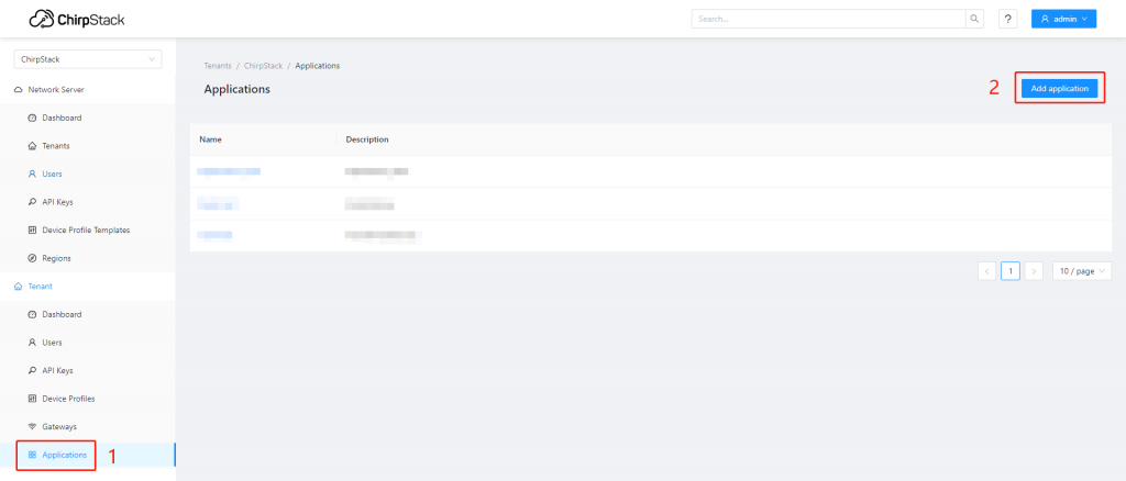
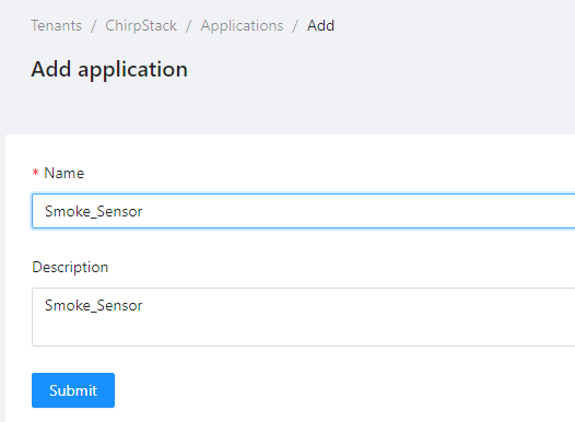
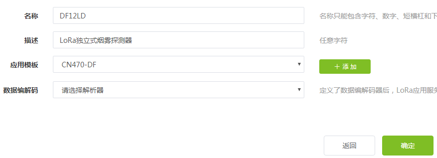
1.3.1 Create an application
After logging into the platform, create a LoRa smoke sensor application. Note: Select “Please select a parser” for “Data codec”, do not select other options.
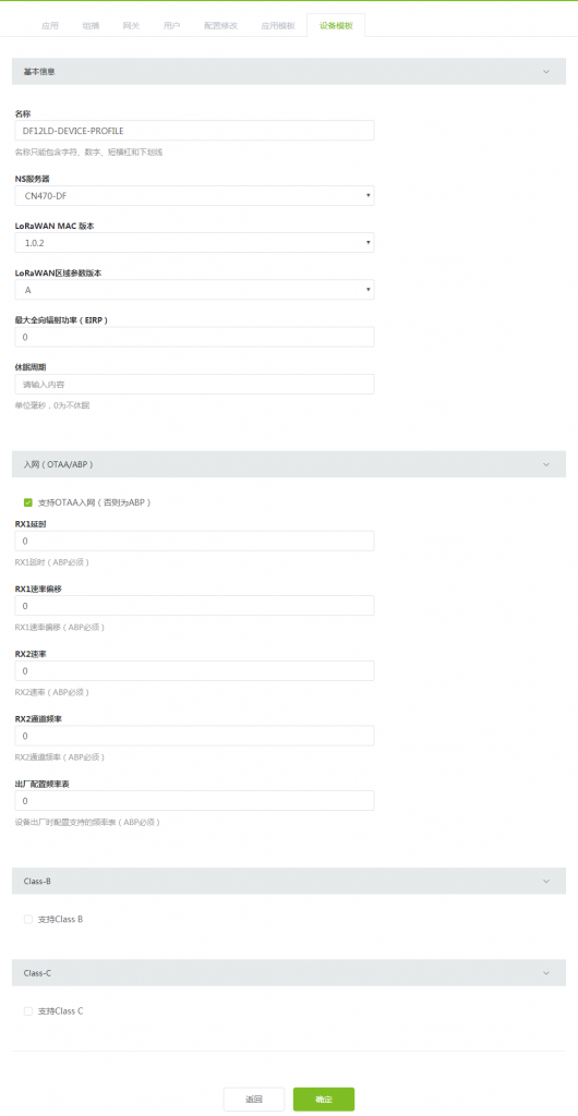
1.3.2 Creating a Device Template
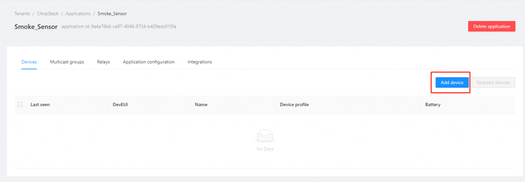
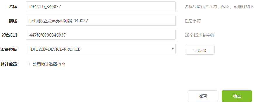
1.3.3 Registering the device
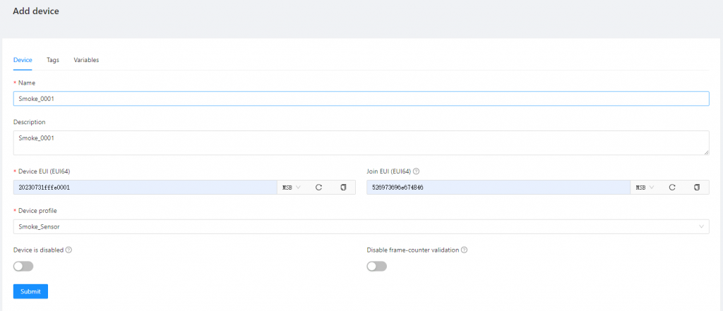
As shown in the figure below, create a device, paste DevEUI on the back of the device, and remove the hanging plate to see it.
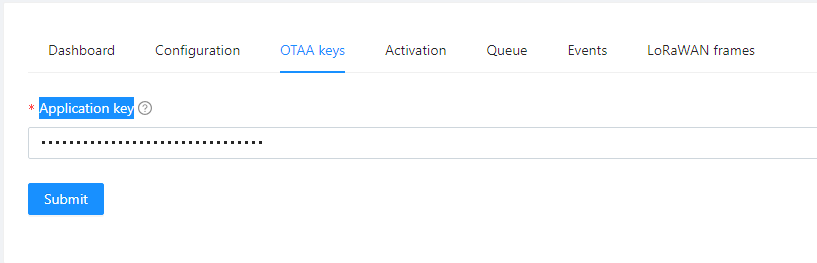
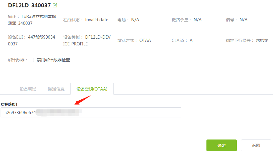
As shown in the figure below, after creating the device, you need to fill in the device key (AppKey, shipped with the product)
1.4 Gateway
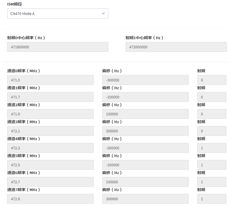
1.4.1 LoRa RF
Log in to the web management page of the gateway and configure the LoRa radio as shown in the figure below. The figure below shows the configuration of CN470 as an example.
1.4.2 LoRa Server
As shown in the figure below, configure the LoRa server.
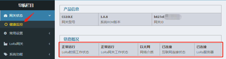
After the above configuration is complete, make sure that the gateway is working normally, as shown in the following figure.
1.5Device
1.5.1Connect Network
The following operations can trigger the device to join the network: 1. Power on the device again. 2. If the device is not connected to the network, press and hold the button for 3s and then release it, and the device will access the network once. The device is successfully connected to the network, and the red LED is always on for 5s. The network connection fails, and the red LED flashes slowly for 5s.
1.5.2 Test Alarm
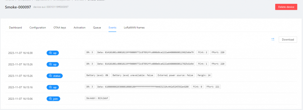
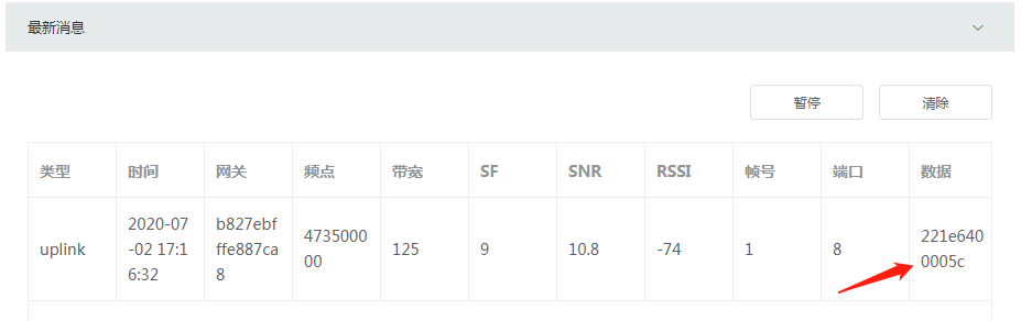
After the device is successfully connected to the network, the alarm test can be performed. Press and hold the button for 3s and release it. During the press and hold, the device will emit sound and light alarms. After releasing, the device will report the test alarm data to the platform through LoRaWAN. As shown in the figure below, please refer to Chapter III for data analysis.
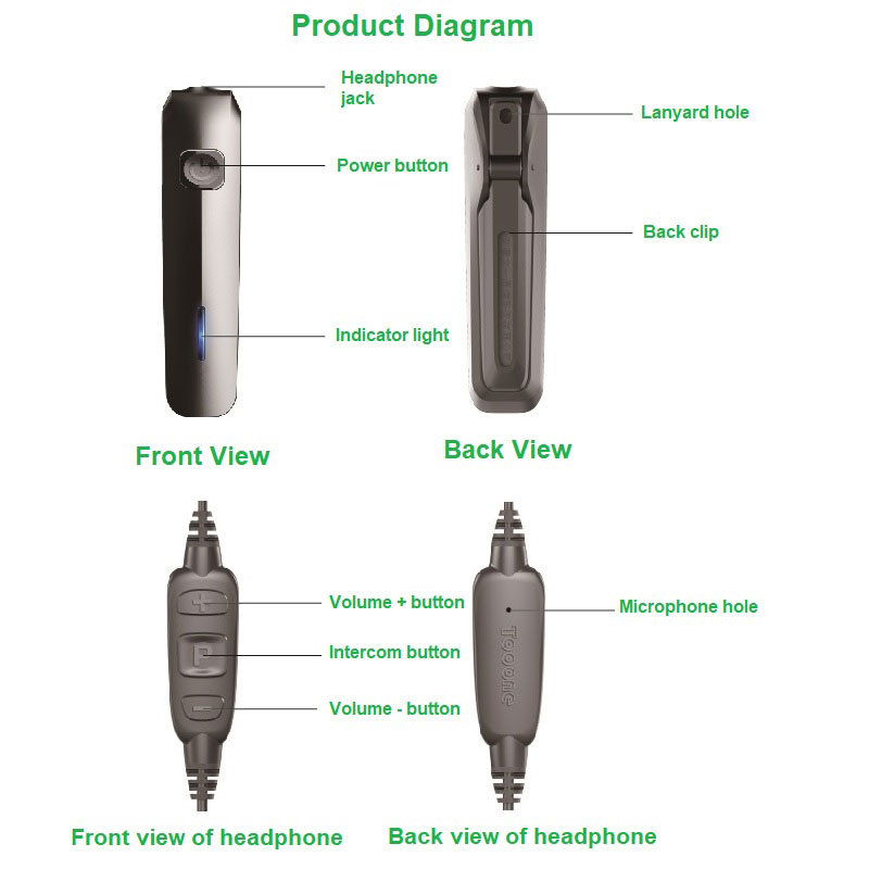
1. Power on: Long press the “Power button” until the red light is on, then release to power on. The voice will broadcast “Welcome to use Tooone Communication Mini Digital Walkie Talkie”. 2. Power off: Long press the “Power button” until the red light is on, then release to power off. The voice will broadcast “Powering off, thank you for using”. 3. Volume adjustment: Plug in the headphone and press the “Volume +/- button” to increase or decrease the volume. The headphone will voice prompt “Volume up/down” and “Maximum/Minimum volume”. 4. Manual intercom: Plug in the headphone and press and hold the “Intercom button”. Speak towards the microphone. The yellow light indicates sending voice. Do not block the microphone hole with finger. 5. Auto intercom: Plug in the headphone and set the working mode to “Auto intercom” as instruction 8. Speak towards the microphone and the device will transmit voice automatically when yellow light is on. 6. Channel prompt: Press the “Power button” once and the voice will broadcast the channel number. 7. Channel switch: Plug in the headphone, press and hold the “Power button” first, then press “Volume +/- button” to cycle through channels incrementally/decrementally. The headphone will prompt channel number during switch. 8. Working mode switch: 1. Plug in the headphone, press and hold the “Intercom button”, then press the “Power button” and release to complete switch. 2. Press the “Power button” continuously three times to complete switch. Press once to exit. 9. Battery prompt: Press the “Power button” twice continuously. The voice will prompt “Battery full”, “Medium battery” or “Battery low, please charge soon”. When battery is critically low, it will prompt “Battery low, powering off” and turn off automatically.
II. Troubleshooting
No. Phenomenon: Cause ;Solution 1. Cannot power on: Low battery; Charge in time 2. Cannot intercom after power on :1) Channelmismatch; Switch channel 2)normally Headphone abnormal ;Change headphone
III. Cautions
1. Please use standard USB power adapter to charge. 2. Please use the original data cable for charging or parameter settings. 3. Please use the original headphone. Third-party headphone will not work. 4. Avoid extreme environment of high temperature, humidity, pollution and radiation. 5. Please operate within the legal frequency bands according to regulations of your country/region.
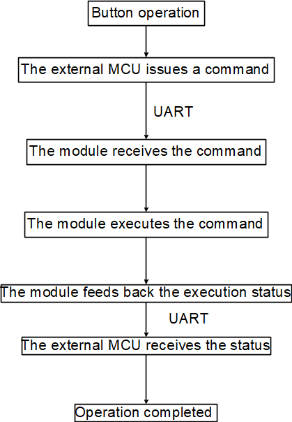
All operations of the module are realized through commands of the external MCU. According to the required operations, the MCU sends corresponding commands to the module through the serial port according to the command table in the command section. The module executes the corresponding commands and feeds back the execution status. The specific process is as follows:
Command
Commands are used to control the module or obtain various working states of the module. When the external circuit sends control commands to the module, the commands include input commands and output commands. The external control CPU receives control commands and returns system status or command execution results.
Under normal circumstances, after receiving the instruction, if the module cannot execute it, it will return an error instruction. Correct execution will return the same instruction to give the control CPU a feedback confirmation. After the module executes the instruction, if the system status changes, it will also return a status instruction.
For example, if the host sends a play channel instruction to the module, after receiving it, if the module is in standby mode, it can play. First, it returns the same instruction to indicate that the instruction has been received and starts executing. Then, the module calls the playback program to play the channel number. At this time, the module will return a playback status instruction. After the playback is completed, the module returns to standby mode and sends a standby status instruction. If the current state of the module is not suitable for playing the channel number, only an error instruction is returned.
The command interface is an asynchronous communication interface, one UART_TX to send and one UART_RX to receive, with a baud rate of 460800, one start bit, 8 data bits, and one stop bit.
The output 0 is a low level and the output 1 is a high impedance. This design is to adapt to a wider interface level, so the input of the control end CPU should be designed as pull-up.
Affected by the driving ability and operating voltage of different control CPUs, the serial signal waveform may be distorted, causing code errors. Therefore, it is recommended to use 2K~10K pull-up resistors on the serial port to ensure signal integrity.
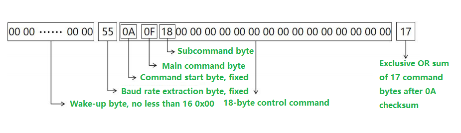
The serial port instruction bytes include three parts: a number of 0s consisting of a wake-up byte, a baud rate extraction byte 0x55, 18 bytes of control commands and 1 checksum byte. The preceding consecutive 0 bytes, the minimum is 16, are used to wake up the main control CPU in sleep mode of the module; the subsequent byte 0x55 measures the baud rate of the serial port for the internal CPU; the subsequent 18 bytes are control commands, starting with 0x0A, followed by 1 byte The main command byte, see Table 4 for specific definitions, the next 16 bytes are command parameter control bytes, if the main command byte is 0x0F, the first byte after it is the sub-command byte, see Table 5 for specific definitions, and the last byte Checksum, which is the exclusive or sum of the 17 bytes after 0x0A. See Figure 2 for details.
Command Table
Num
Command
I/O
Definition
Parameter bytes
Note
1
0x0F
I
Control command
Combine control subcommands to implement various control functions, status reading and feedback
See the subcommands table
2
0xC3
IO
Write working mode
Current working mode, maximum working mode channel number, working channel
3
0x 03
IO
Read working mode
Current working mode, maximum working mode channel number, working channel
4
0x CF
IO
Change specified channel parameters
Change the working frequency and transmit power of the specified channel
5
0x 3F
IO
Read specified channel parameters
Read the working frequency and transmit power of the specified channel
6
0x A5
IO
Control password modification
Control password, new control password
7
0x CA
IO
Write super password
Control password, super password
8
0x 3A
IO
Read super password
Control password, super password
9
0x 5A
IO
Voice command
16-byte voice data
10
0x 55
IO
Data command
Up to 15 bytes of data in a single command, and the 16th byte is the valid data length
All commands to change, read, and report the working status of the module are called control commands, and the command byte is 0x0F. Immediately following the command byte is one byte of control subcommand. The 15 bytes after the subcommand are control parameters, used in sequence, with the lower bits first.
The interface design between the module and the module follows the following principles: The output interface relative to the module must be set to open drain; The input interface relative to the module must be set to pull-up.
Subcommand table of module control commands
Num
Subcommands
I/O
Definition
Parameter bytes
Note
1
0x11
IO
Read the working state
Working status (0: Standby; 1: Playback; 2; Transmit only; 3: Receive only; 4: Transceiver; 5: USB; 6: Error; 7: Test; 8: Other modes) Software information acquisition (0x80: Obtain software information)
2
0x12
O
Report working status
Working status (0: Standby; 1: Playback; 2; Transmit only; 3: Receive only; 4: Transceiver; 5: USB; 6: Error; 7: Test; 8: Other modes) Software information acquisition (0x80: Obtain software information)
3
0x18
IO
Transmit control
Enter the transmit state, the first byte is the working channel, default 00 indicates the current channel, such as 0xAA indicating the activation of VOX intercom mode; the second byte is the sound playback mode: 0: internal playback; 1: digital voice mode
Equivalent to a PTT press
4
0x16
IO
Standby
The first byte is the standby channel number The second byte is the sound playback mode: 0: internal playback; 1: digital voice mode; 2: so-called mixed mode, internal playback and digital voice output
Used with PTT to stop transmission; the first byte function is currently not supported, default is 0
5
0x14
I
Playback commands
Play data voice
Used in conjunction with digital voice commands
6
0x1B
O
Send success
Data send success instruction
Used in conjunction with data commands
7
0xF5
IO
Instruction error
Control and current status do not match
8
0x31
IO
Volume up
Current volume value 0~15, 15 maximum
9
0x32
IO
Volume down
Current volume value 0~15, 15 maximum
10
0x34
IO
Channel plus
Current channel value, maximum channel number set by mode setting command
Ensure that the parameters of each channel are set correctly
11
0x37
IO
Channel minus
Current channel value, maximum channel number set by mode setting command
Ensure that the parameters of each channel are set correctly
12
0x39
IO
Low battery warning
Battery voltage, occupying two bytes
Unit: millivolt
13
0x38
IO
Normal battery
Battery voltage, occupying two bytes
Unit: millivolt
14
0x3B
IO
Voice broadcast
0: Battery power, 1: Channel, 2: Channel mode
15
0x41
IO
VGA setup
Microphone gain level value (default 4)
0~15 levels, the larger the value, the greater the gain
16
0x42
IO
VGA read
Microphone gain level value (default 4)
0~15 levels, the larger the value, the greater the gain
17
0x51
IO
Threshold setting
VOX trigger sensitivity, that is, voice threshold level value (default 0)
0~7 levels, the smaller the value, the more sensitive, that is, the lower the threshold
18
0x52
IO
Threshold reading
VOX trigger sensitivity, that is, voice threshold level value (default 0)
0~7 levels, the smaller the value, the more sensitive, that is, the lower the threshold
Standard: defines the working mode. The high four bits are valid. Intercom mode (0x00), repeater mode (0x10), intercom + repeater mode (0x20).
OpMode: defines the channel mode of the intercom. The current channel modes are: 4-channel mode (0x04), 6-channel mode (0x05), 8-channel mode (0x06). The 4-channel mode has the best voice quality.
Language: Currently, only two languages are supported. 0 indicates Chinese and 1 indicates English;
ChannelMax: Maximum number of channels, that is, the total number of channels;
LocalChannel: Current working channel, starting from 0;
Group: Occupies two bytes, low bit first, indicates the group number, maximum 999;
LocalNum: Occupies two bytes, low bit first, indicates the number within the group, maximum 999. The group number and the number within the group constitute the local number of the intercom. The intercom can communicate with each other in groups with the same group number. LocalNum cannot be 0;
Priority: Priority, a total of 2 levels, 3 is high priority, 0 is low priority. Priority is valid after priority reservation is opened.
HotChannel[4]: Hot call channel, full duplex version does not have this function.
PhoneSpecial[2]: Important control parameters, used to control various enable states, including transmission enable, priority reservation enable, etc., specifically as follows: struct PhoneSpecialDef{ unsigned short SideToneEn:1; //Default is 0, modification is invalid unsigned short MultistardardEn:1; //Default is 0, modification is invalid unsigned short TXPowerADJEn:1; //Default is 0, modification is invalid unsigned short VOXAdjEn:1; //Default is 0, modification is invalid unsigned short HotChannelEn:1; //Default is 0, modification is invalid unsigned short TXEn:1; //Transmission enable, default is 1, disable transmission is 0 unsigned short ModeADJEn:1; //Default is 1, modification is invalid unsigned short MultiChannelEn:1;//Default is 0, modification is invalid unsigned short Battery_Alarm_EN:1; //Low battery warning enable, 0–close, 1–open unsigned short Master_Reserve_En:1; //Priority reservation enable, default is 0, open is 1 };
Low bit first, high bit last. For example, transmission allowed PhoneSpecial[1] is 0x60, transmission prohibited 0x40, priority reservation open PhoneSpecial[2] is 0x02, close is 0x00.
Channel parameter read and write data structure
The channel parameter read and write command specifies the read and write of the related parameters of the specified channel. The read command must attach the channel number, and other parameters are empty.It should be noted that the specified channel is not necessarily the current working channel.The channel parameter read and write data occupies the data bytes after the command. The structure definition is as follows: struct{ unsigned char Channel; //0 unsigned char Freq[4]; //1~4 unsigned char Target[2]; //5~6 unsigned char TXPower; //7 }MK_Channel;
Channel: indicates the specified channel number; Freq: is the working frequency value, occupying 4 bytes, low byte first, unit is Hz; Target: refers to the called intercom number of this channel. When Target is 0, all intercoms can receive it. When Target is not 0, only the number specified by Target can hear it. Using this function, point-to-point or point-to-multipoint intercom functions of the intercom can be realized; TXPower: refers to the transmit power, in dBm, the control range of TMK01/04 is 0~21dBm; TMK02 is 20~28dBm.
The VGA parameter data structure
VGA parameter read-write data occupies 1 byte of data behind the command. the structure is defined as follows: struct{ unsigned char Sub_Command; //0 unsigned char VGA; //1 }MK_VGA Sub_Command is the subcommand, see the Subcommand table for details; VGA is the data byte. According to the subcommand byte, it is the mic gain level.
The VOX parameter data structure
The VOX parameter read and write data occupies 1 byte of data behind the command, and the structure is defined as follows: struct{ unsigned char Sub_Command; //0 unsigned char VOX_GRADE; //1 }MK_VOX_GRADE Sub_Command is the subcommand, see the Subcommand table for details; VOX_GRADE is the data byte. According to the subcommand byte, it is the VOX trigger sensitivity, that is, the voice threshold level value.
Encryption key parameter data structure
The encryption key parameter read and write data occupies 1 data byte after the command. The structure definition is as follows: struct{ unsigned char ConnectCode[4]; //1,2,3,4 unsigned char KEY[4]; // 5,6,7,8 unsigned char KEY2[4]; // 9,10,11,12 }MK_Key; ConnectCode[4] is the current four-digit login key, which can be used as the connection key to connect the management system software. KEY[4] and KEY2[4] are two groups of four-digit keys to be modified. According to the command byte, they are communication keys.
Channel selection data structure
Current selected channel data occupies 1 data byte behind the command, the structure is defined as follows: struct{ unsigned char Sub_Command; //0 unsigned char UsedChannel; //1, }MK_CHN_Command; Sub_Command is the subcommand, see the Subcommand table for details; UsedChannel is the data byte. According to the subcommand byte, it is the current working channel.
Volume parameter data structure
Volume parameter read and write data occupies 1 data byte behind the command, and the structure is defined as follows: struct{ unsigned char Sub_Command; //0 unsigned char SPK_Volume; //1, }MK_SPK_Command; Sub_Command is the subcommand, see the Subcommand table for details; SPK_Volume is the data byte. According to the subcommand byte, it is the current volume level. Levels 0 to 15 can be set.
Working software information data structure
Each working software information data reply code occupies 14 bytes. The structure definition is as follows: struct{ unsigned char Sub_Command; //0 unsigned char Sub_Command_Soft; //1, unsigned char Soft[14]; //2~15 }MK_SPK_Command; Sub_Command is a subcommand, 0x11, see the Subcommand table for details; Sub_Command_Soft is a working software information command header, 0x80~0x8A, see 8.11 example; Soft [14] is a data byte, turn to ASCII value, including Chinese characters, for more details see the Control command example .
Digital voice
The digital voice sampling rate is 8K, and each sample occupies 16 bits (a short integer, signed short). During transmission, one serial port frame is 16 bytes, equivalent to 1ms of sampled voice. When using digital voice, the additional parameters should be set to digital voice mode at the same time when controlling the transmission, and the digital voice should be continuous. Every 20 milliseconds, 20 frames of digital voice should be provided. When the receive standby mode is set to digital voice or mixed mode (see the Subcommand table , the standby additional voice mode parameter is 1 or 2), the module will output digital voice at the speed of sending 20 frames every 20 milliseconds. The voice is the original sampled voice and can be played directly or saved.
Data transmission
The module provides data transmission function, using the data command (0x55) in Table 4 for communication. The data length is 16 bytes, the first 15 bytes are data content, and the 16th byte is the valid data length. The sender can send up to 15 bits of data in a single data command. When the data to be sent is greater than 15 bits, the data should be divided into packets of 15 bits per command and transmitted to the module. The module will automatically connect and send out the sender information. for more details see the Control command example . The sender information includes the send mode and the local number, the send mode has two types: broadcast and private, the high bits of 2 bytes, 0 is broadcast, 1 is private, the low 10 bits are the local number, the send mode is determined according to the call number, when the call number is 0, it is broadcast, otherwise it is private.When using the data transmission function, the next data should be sent after receiving the transmission success reply code (0x1B). The 15-bit data content of the receiver will include 2 parts, the first 2 bytes are the sender information, and the last 13 bytes are the data content. Data transmission can be performed in any state, such as intercom transmission, intercom reception, standby; but when the number of channels is occupied, it cannot be sent, the same as the intercom function. When transmitting data in intercom transmission state, a certain amount of voice bandwidth needs to be occupied. When used at the same time, it will reduce voice quality. It is not recommended to conduct large-scale data transmission. In addition, to ensure accurate data transmission, it is recommended that the transmission interval be greater than 100ms.
Control command example
1. Query mode parameters Ask: 00 00 00 00 00 00 00 00 00 00 00 00 00 00 00 00 55 0A 03 00 00 00 00 00 00 00 00 0000 00 00 00 00 00 00 03 Answer: 00 00 55 0A 03 20 04 10 1E 05 78 03 78 03 07 06 07 08 09 60 00 4B Explanation: 00 is the wakeup byte, 0x55 allows the internal CPU to measure the baud rate of the serial port, 0x0A is the start byte, 0x03 is the read parameter instruction byte,0x20 is the Standard parameter, indicating that the current mode is intercom + repeater, 0x04 is the OpMode parameter, the high four bits cannot be changed, the low four bits are valid, 04 indicates four-channel mode,0x10 is the Language parameter, the high four bits cannot be changed, the low four bits are valid, 10 indicates Chinese, 0x1E is the ChannelMax parameter, the default is 30 channels, 0x05 is the LocalChannel parameter, the default is channel 6, The first 0x78 0x03 is the Group parameter, the low bit comes first, the default is 888, The second 0x78 0x03 is the LocalNum parameter, the low bit comes first, the default is 888 0x07 is the Priority parameter, the default is the highest level,0x06 0x07 0x08 0x09 are the HotChannel parameters, multi-party mode does not have this function, modification is invalid, 0x60 0x00 are the enable parameters, refer to the parameter definitions, TXEn (transmit enable) and ModeADJEn (mode change enable) are turned on, you can transmit and modify the operating mode, the others are 0, closed, need to turn on 1 when using.
2. Modify mode parameters Ask: 00 00 00 00 00 00 00 00 00 00 00 00 00 00 00 00 55 0A C3 10 04 10 1E 08 78 03 78 03 07 00 00 00 00 60 01 B7 Answer: 00 00 55 0A C3 10 04 10 1E 08 78 03 78 03 07 00 00 00 00 60 01 B7 Explanation: 00 is the wakeup byte, 0x55 allows the internal CPU to measure the baud rate of the serial port, 0x0A is the start byte, 0xC3 is the write parameter instruction byte, 0x10 is the Standard parameter, set to repeater mode, 0x04 is the OpMode parameter, the high four bits cannot be changed, the low four bits are valid, set to four-channel mode, 0x10 is the Language parameter, the high four bits cannot be changed, the low four bits are valid, set to Chinese,0x1E is the ChannelMax parameter, set to 30 channels, 0x08 is the LocalChannel parameter, set to channel 9,The first 0x78 0x03 is the Group parameter, the low bit comes first, set to 888, The second 0x78 0x03 is the LocalNum parameter, the low bit comes first, set to 888 0x07 is the Priority parameter, set to the highest level, 0x60 01 are the enable parameters, refer to the parameter definitions, TXEn (transmit enable), ModeADJEn (mode change enable), and Master_Reserve_En (priority reservation enable) are turned on, you can transmit, modify the operating mode, priority function is turned on, others are 0, closed.
3. Query specified channel parameters Ask: 00 00 00 00 00 00 00 00 00 00 00 00 00 00 00 00 55 0A 3F 05 00 00 00 00 00 00 00 0000 00 00 00 00 00 00 3A Answer: 00 00 55 0A 3F 05 F3 43 2A 1C 78 03 14 03 07 00 00 00 00 60 01 B6 Explanation: 00 is the wakeup byte, 0x55 allows the internal CPU to measure the baud rate of the serial port, 0x0A is the start byte, 0x3F is the read channel parameter instruction byte, 0x05 is the Channel parameter, read the specified channel, channel 6, 0xF3 0x43 0x2A 0x1C is the Freq parameter, the low bit comes first, 472531955Hz, 0x78 0x03 is the Target parameter, the low bit comes first, 888, 0x14 is the TXPower parameter, 20dBm. The following 03 07 00 00 00 00 60 01 bytes do not need to be considered, they are part of the module buf that has not been cleared.
4. Modify specified channel parameters Ask: 00 00 00 00 00 00 00 00 00 00 00 00 00 00 00 00 55 0A CF 05 F3 43 2A 1C 78 03 14 00 00 00 00 00 00 00 00 23 Answer: 00 00 55 0A CF 05 F3 43 2A 1C 78 03 14 03 07 00 00 00 00 60 01 46 Explanation: 00 is the wakeup byte, 0x55 allows the internal CPU to measure the baud rate of the serial port, 0x0A is the start byte, 0xCF is the write channel parameter instruction byte, 0x05 is the Channel parameter, write to the specified channel, channel 6, 0xF3 0x43 0x2A 0x1C is the Freq parameter, the low bit comes first, 472531955Hz, 0x78 0x03 is the Target parameter, the low bit comes first, 888, 0x14 is the TXPower parameter, 20dBm. The following 03 07 00 00 00 00 60 01 bytes do not need to be considered, they are part of the module buf that has not been cleared.
5. Intercom transmission Ask: 00 00 00 00 00 00 00 00 00 00 00 00 00 00 00 00 55 0A 0F 18 00 00 00 00 00 00 00 0000 00 00 00 00 00 00 17 Answer: 00 00 55 0A 0F 18 00 0F 00 00 00 00 00 00 00 00 00 00 00 00 00 18 00 00 55 0A 0F 12 03 0F 00 00 00 00 00 00 00 00 00 00 00 00 00 11 00 00 55 0A 0F 12 04 0F 00 00 00 00 00 00 00 00 00 00 00 00 00 16 Explanation: 00 is the wakeup byte, 0x55 allows the internal CPU to measure the baud rate of the serial port, 0x0A is the start byte, 0x0F is the control command main command byte, 0x18 is the control command transmit control subcommand byte (see Table 5 for details); the first reply is the same command returned after the command is executed correctly, and the second and third are current status reporting commands, 0x12 is the status subcommand byte, 0x03 and 0x04 are receive and transmit status ( see the Subcommand table for details ).
6. Exit intercom Ask: 00 00 00 00 00 00 00 00 00 00 00 00 00 00 00 00 55 0A 0F 16 00 00 00 00 00 00 00 0000 00 00 00 00 00 00 19 Answer: 00 00 55 0A 0F 16 02 00 00 00 00 00 00 00 00 00 00 00 00 00 00 1B 00 00 55 0A 0F 12 00 00 00 00 00 00 00 00 00 00 00 00 00 00 00 1D Explanation: 00 is the wakeup byte, 0x55 allows the internal CPU to measure the baud rate of the serial port, 0x0A is the start byte, 0x0F is the control command main command byte, 0x16 is the control command standby subcommand byte (see Table 5 for details); the first reply is the same command returned after the command is executed correctly, and the second is the current status reporting command, 0x12 is the status subcommand byte, 0x00 is the standby status ( see the Subcommand table for details).
7. Intercom mode sends data command Example 1 Send: 00 00 00 00 00 00 00 00 00 00 00 00 00 00 00 00 55 0A 55 01 02 03 04 05 06 07 08 00 00 00 00 00 00 00 08 55 Reply: 00 00 55 0A 0F 1B 00 0F 00 00 00 00 00 00 00 00 00 00 00 00 1B 00 00 55 0A 0F 12 03 0F 00 00 00 00 00 00 00 00 00 00 00 00 00 11 00 00 55 0A 0F 12 04 0F 00 00 00 00 00 00 00 00 00 00 00 00 00 16 00 00 55 0A 0F 12 00 0F 00 00 00 00 00 00 00 00 00 00 00 00 00 12 Receiver: 00 00 55 0A 55 78 83 01 02 03 04 05 06 07 08 2A 1C 78 03 14 08 F7 Explanation: 00 is the wakeup byte, 0x55 allows the internal CPU to measure the baud rate of the serial port, 0x0A is the start byte, 0x55 is the data command byte. The last byte 0x08 in the sender’s data is the number of valid data bytes, i.e. 8 bytes of data, the 8 bytes after 0x55; 0x1B in the reply indicates that the module has received the data and sent successfully. The data received by the serial port of the receiver, 0x78 0x83 is the sender information, the low bit is in front, the highest bit is 1, at this time it is private send mode, the low 10 bits are the local number, that is, 888, the checksum before 0x08 is the number of valid data bytes, that is, 8 bytes of data, the 8 bytes after the sender information; the content of 2A 1C 78 03 14 in the command is the unused part of the module buf, which is also invalid data and does not need to be considered. Note: The data content should fill in the last valid data count. The receiver obtains the data content according to this count.Example 2 Send: 00 00 00 00 00 00 00 00 00 00 00 00 00 00 00 00 55 0A 55 11 12 13 14 15 16 17 18 19 20 21 22 23 24 25 0F 4A Reply: 00 00 55 0A 0F 1B 05 10 1E 05 78 03 78 03 06 00 00 00 00 60 02 7E 00 00 55 0A 0F 12 03 10 1E 05 78 03 78 03 06 00 00 00 00 60 02 71 00 00 55 0A 0F 12 04 10 1E 05 78 03 78 03 06 00 00 00 00 60 02 76 00 00 55 0A 0F 12 00 10 1E 05 78 03 78 03 06 00 00 00 00 60 02 72 Receiver: 00 00 55 0A 55 78 83 11 12 13 14 15 16 17 18 19 20 21 22 23 0D B2 00 00 55 0A 55 78 83 24 25 00 00 00 00 00 00 00 00 00 00 00 02 AD Explanation: The sender sends out 15 valid data. Because the receiver data contains 2 bytes of sender information, each data command can contain a maximum of 13 valid data. Therefore, the receiver receives two data commands. Other command content explanations are the same as Example 1.
8. Software information acquisition command Send: 00 00 00 00 00 00 00 00 00 00 00 00 00 00 00 00 55 0A 0F 11 80 00 00 00 00 00 00 0000 00 00 00 00 00 00 9E Reply: 00 00 55 0A 0F 11 80 D2 D7 BA F4 B1 A6 4D 31 2D 4D 2F 45 2D 54 8F 00 00 55 0A 0F 11 81 61 6C 6B 69 65 2D 4D 31 2D 4D 20 56 33 2E 8E 00 00 55 0A 0F 11 82 30 2E 33 5F 34 38 30 4D 48 7A 2C 20 43 6F 8D 00 00 55 0A 0F 11 83 70 79 72 69 67 68 74 28 43 29 20 62 79 20 8C 00 00 55 0A 0F 11 84 54 6F 6F 6F 6E 65 2C 32 30 32 33 2E 30 34 8B 00 00 55 0A 0F 11 85 2E 30 34 00 00 00 00 00 00 00 00 00 00 00 8A Explanation: 00 is the wakeup byte, 0x55 allows the internal CPU to measure the baud rate of the serial port, 0x0A is the start byte, 0x55 is the data command byte, 0x11 is the status acquisition instruction, and 0x80 is the parameter byte for acquiring software information. In the reply, the 14 bytes after 0x11 and 0x80 are software information. Because the complete software information is longer than 14 bytes, the subsequent 0x81, 0x82, 0x83, 0x84, and 0x85 all contain 14 bytes of software information until 0x00 ends. The data needs to be converted to ASCII values, including Chinese characters, for example: D2 D7 BA F4 B1 A6 4D 31 2D 4D 2F 45 2D 54 61 6C 6B 69 65 2D 4D 31 2D 4D 20 56 33 2E 30 2E 33 5F 34 38 30 4D 48 7A 2C 20 43 6F 70 79 72 69 67 68 74 28 43 29 20 62 79 20 54 6F 6F 6F 6E 65 2C 32 30 32 33 2E 30 34 2E 30 34; converted to ASCII values is: Yihubao M1-M/E-Talkie-M1-M V3.0.3_480MHz, Copyright(C) by Tooone,2023.04.04.
Design tips for the main control ports
In order to shorten the secondary development cycle of the module as much as possible, the module provides several direct control ports to facilitate rapid function implementation during design by bypassing UART commands. The following details the main design points of the main control ports.
USB interface
The USB interface realizes two functions: one is module software upgrade, and the other is parameter modification. Connect USB before power-on, the module automatically enters the upgrade mode. Users can download the corresponding control software from our company website to realize software upgrade and parameter modification. If software upgrades and parameter modifications are not allowed for end users in secondary development, the USB interface does not need to be connected. However, in order to prevent bugs that need to be upgraded in the module and the end user experience, it is recommended that USB interfaces be retained as much as possible in secondary development products.
Software upgrade When the module is powered off and connected to USB and computer, it enters the software state after power-on, and software upgrade can be performed. Parameter setting After the module is powered on, it is connected to USB and computer by default. The default is charging mode only. You need to send USB parameter mode instructions (0x0F 0xC1) via serial port to enter parameter mode to set parameters via USB interface.
UART interface The UART interface is a control interface specially provided for secondary development. All control functions can be realized through the instructions of the UART interface. It should be noted that the receiving end of the user CPU’s UART needs to be set to pull-up mode, and the sending end port needs to be set to open drain mode. It should be specially noted that in addition to the UART interface, the user’s other control interfaces can be completely unused, and all controls can be realized through UART.
Circuit design example
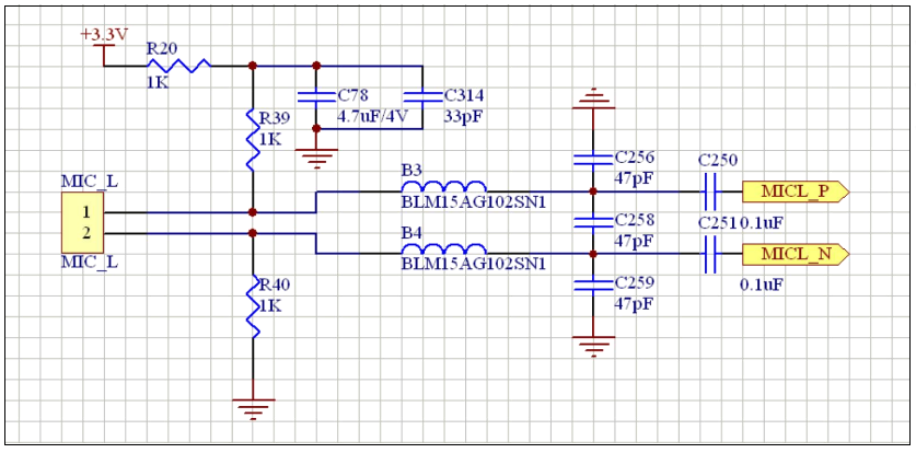
In order to shorten the secondary development cycle of the module as much as possible, the company provides examples of some design circuits for reference. Microphone circuit design It is recommended to use differential input for microphones. In this case, the microphone pins of the module can be directly connected. A common electret microphone can use the following circuit:[A circuit diagram showing a microphone connected to a module through capacitors.]C1 and C2 are DC blocking capacitors, R1 is a pull-up resistor, and R2 is used to adjust the microphone sensitivity. The microphone output is connected to the MIC+ and MIC- pins of the module. MIC+ is the signal input end, and MIC- is the reference ground end. Adding a capacitor C3 in parallel on the microphone can enhance the low frequency response.The parameters in the figure are for reference only. C1 and C2 are generally around 1uF. R1 takes 10K, and R2 takes around 1K-4.7K. C3 takes around 0.1uF-0.47uF. The specific parameters should be adjusted according to the actual microphone sensitivity.The schematic in the figure uses a single power supply. For designs with positive and negative power supplies, MIC- should be connected to the negative power supply.
Microphone circuit
Notes: C250 and C251 can be left unconnected, C78 can use a 10uF capacitor, and 3.3V can range from 2V to 3.3V and needs to be independent or clean.
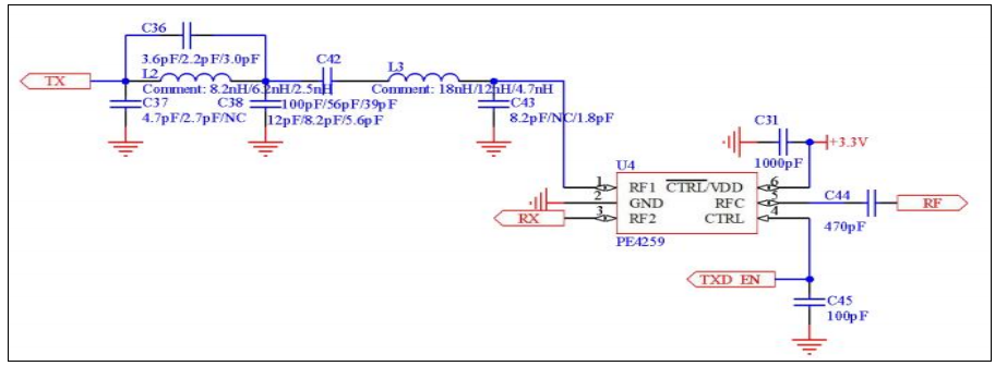
RF management circuit diagram TMK01 needs to manage and match the RF transmission and reception. The following figure shows the recommended example of the TMK01 RF management and matching circuit. The three values marked in the figure correspond to frequencies of 480MHz, 650MHz and 915MHz respectively.
TMK01 RF Matching Circuit
Notes: This is a recommended circuit for RF matching. Antenna matching needs to be matched according to the actual structure and circuit. You can communicate with antenna manufacturers.
[A circuit diagram showing RF filters and matching circuits connected to a module.]This circuit uses band-pass filters to filter out unwanted frequencies and impedance matching circuits to match the 50 ohm impedance. The specific parameters should be adjusted according to the actual frequency used.The RF output of the TMK01 module needs to be managed and matched to achieve the optimal working state. If the RF part is improperly designed or unmatched, it may cause low power, poor anti-interference ability, reduced communication distance, and unstable working state.
Other circuits The speaker is differential output. SPK_P and SPK_N can be directly connected to both ends of the speaker. For single-ended use, a DC blocking capacitor (not less than 220uF) needs to be added. Other circuits can refer to the circuit design of the demo board. Please contact thetechnical support for a copy if needed(sales@dwmzone.com).
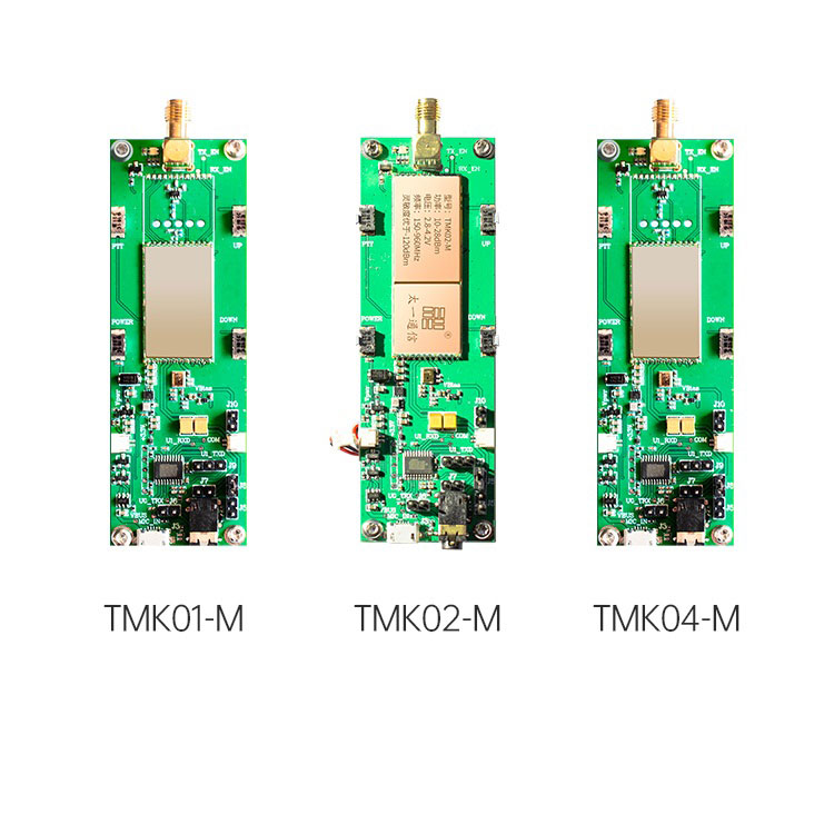
The company provides a full set of module development tools for a fee, including a development board (including TMK01-M or TMK02-M or TMK04-M), Demo software, circuit diagrams, demonstration software, test accessories (USB data cable, serial communication cable, antenna, battery, wired headset, etc.). Users can purchase according to the contact information below.The development board is a simple walkie-talkie that contains four control buttons. Three of the buttons, the PTT button, UP button and DOWN button, are directly connected to the corresponding ports of the module. After power-on, all the corresponding control functions can be realized. The fourth button is the POWER button, which is used to turn the power on and off: press and hold until the red light turns on to turn on the power, and press and hold until the blue light turns red to turn off the power. In addition to the power interface, the development board also includes a USB port, headset interface and speaker output port. In addition to the power interface, the development board also includes a USB port and speaker output port.
development board
The USB interface can be used to upgrade the module software. The upgrade method is: turn off the power supply. Connect the USB cable to the computer, turn on the power supply, the module will automatically enter the upgrade mode after power-on, and you can use the host computer software to upgrade the software. The headset interface uses an ordinary walkie-talkie Y-headset to answer and talk, and supports wire control functions. The wire control function on the development board is not implemented by the module itself, but is controlled by the control CPU monitoring the wire control status and controlling the module through PTT control instructions. Users can freely design according to their own circuit design. Another function of the headset interface is to demonstrate instruction control. All walkie-talkie states and control instructions can be transmitted through this interface. At this time, the control CPU only performs transparent transmission of UART instructions, which is equivalent to directly controlling the module with the host computer. The control CPU will monitor status instructions and display the module status through lights: the blue light flashes periodically to indicate standby; the green light indicates playback; the yellow light indicates sending or receiving; the green light flashes to enter the test mode. It should be specially noted that the headset interface uses a universal Y-head walkie-talkie write frequency line on the market. The transmission and reception of the write frequency line reuse the same line, so when sending instructions, the same instructions will be received at the same time, plus the module feedback instructions will receive two identical return instructions. If the instruction is that the module status has changed, additional module output status report instructions will also be received.
Special statement
The module can be used with TMK05-M. Set TMK05-M to repeater mode to increase communication distance. The module adopts deep software and hardware hybrid encryption technology. Any intrusive test (such as opening the shield cover for testing) may cause software loss and hardware damage, causing the module to fail.Notes:1. The TMK05-M is a signal repeater module that can be used with the main module (TMK01/TMK02/TMK04) to increase communication distance by relaying signals. Set the TMK05-M to repeater mode in order to work with the main module.2. The module uses advanced encryption techniques involving both software and hardware. Any unauthorized access or tampering of the module could damage the software and hardware, causing the module to malfunction. Users should avoid directly accessing components under the shielding.