Pre-Work: Gateway Setting
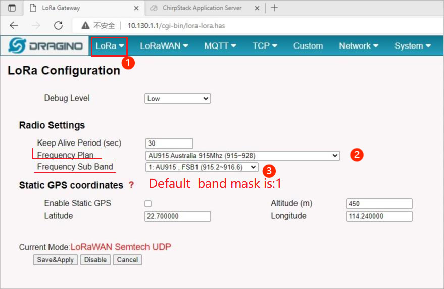
Radio Setting
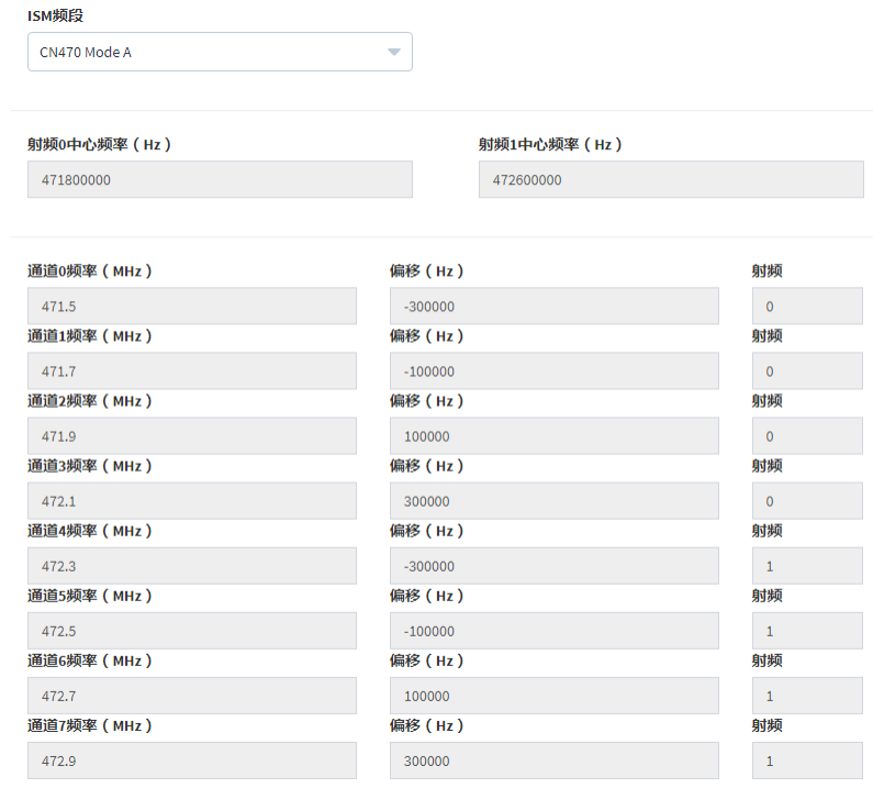
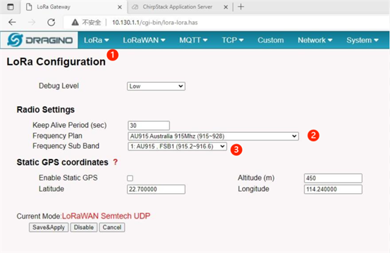
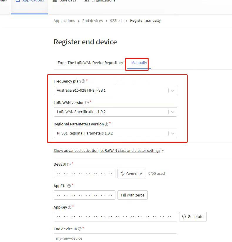
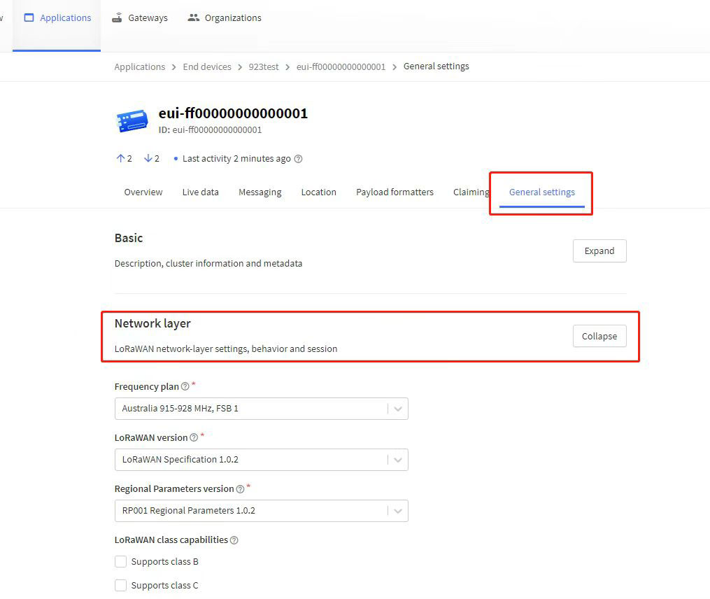
Log in to the web management page of the gateway and configure the LoRa radio as shown in the figure below. The figure below shows the configuration of U915 as an example.
The default working frequency of the Smoke Sensor is 0 to 7 channels in the US915 band, and the corresponding frequency points are shown in the following figure.
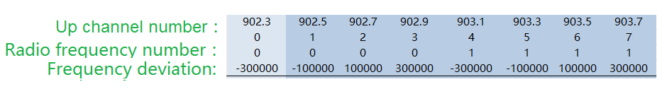
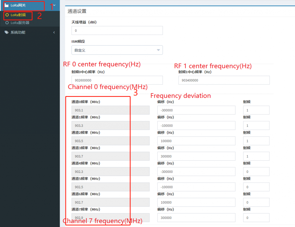
RF 0 center frequency: 902.6MHz, RF 1 center frequency: 903.4MHz,
The corresponding frequency points are 902.3, 902.5, 902.7, 902.9, 903.1, 903.3, 903.5, 903.7 (Unit: MHz)
LoRa Gateway Server Setting
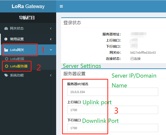
Configure the LoRa server
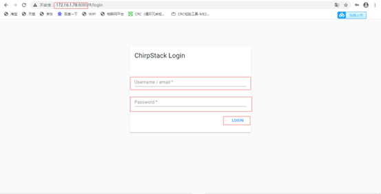
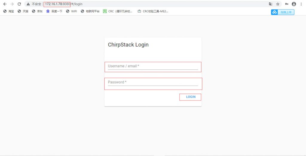
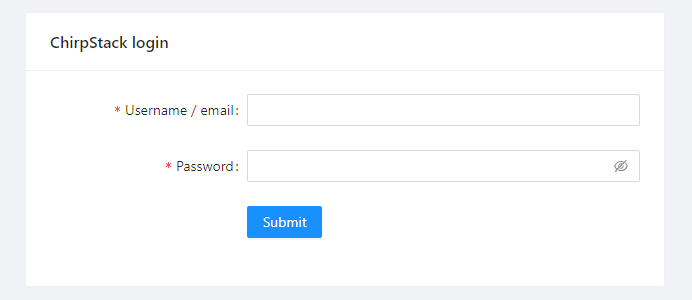
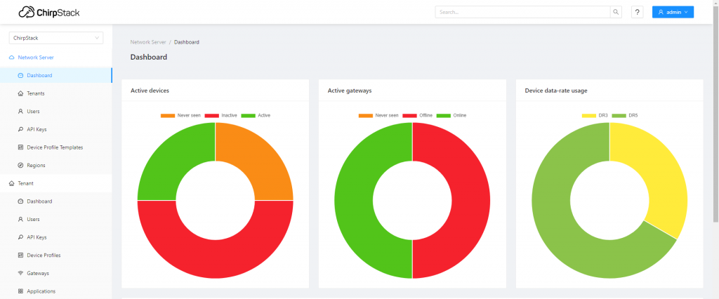
1. Login to ChirpStack
In the browser address bar, enter the ChirpStack server address, then enter your account and password to log in.
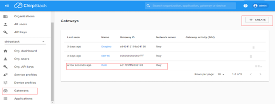
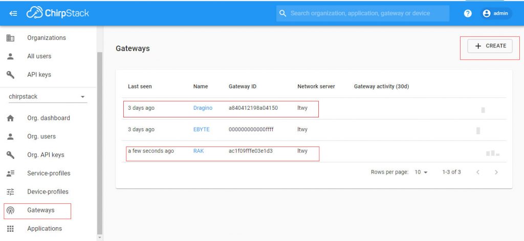
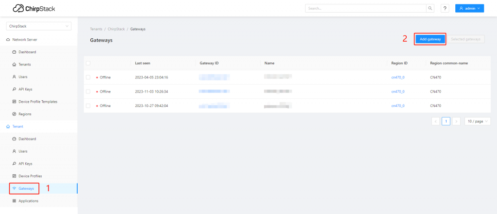
2. Add Gateway
Go to “Gateways”, click “Add gateway” in the top right corner to add a gateway.
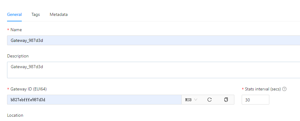
Description: Gateway description;
Gateway ID: Enter the gateway EUI, fill in according to the actual situation;
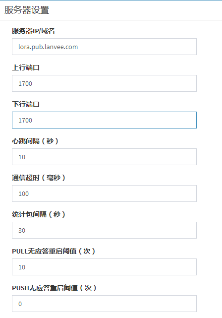
Stats interval: The interval at which the gateway sends statistics, unit: s;
Fill in the required gateway information to be added, then click “Submit”.
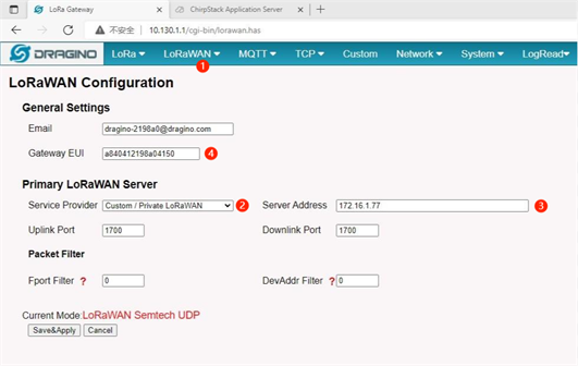
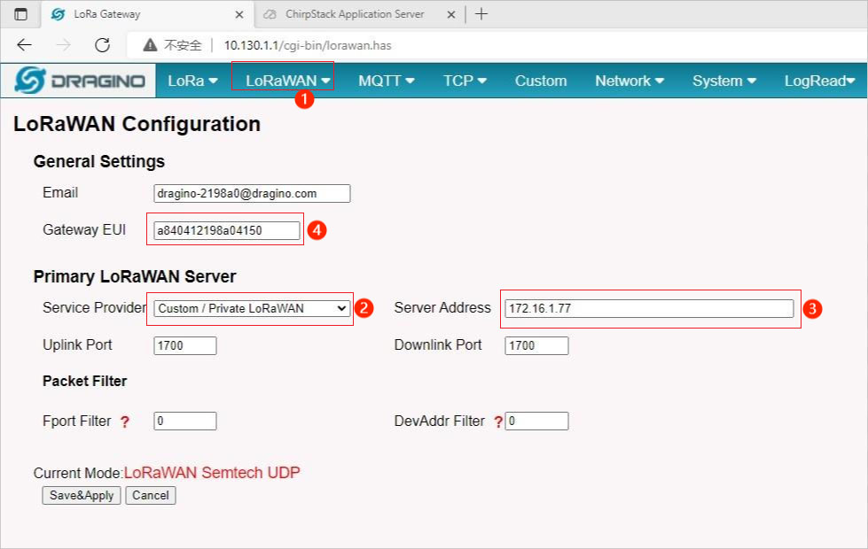
3. Gateway configuration
Log in to the gateway’s configuration page, fill in the actual ChirpStack server address and uplink/downlink ports according to the actual information of the ChirpStack server.
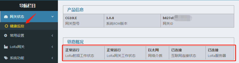
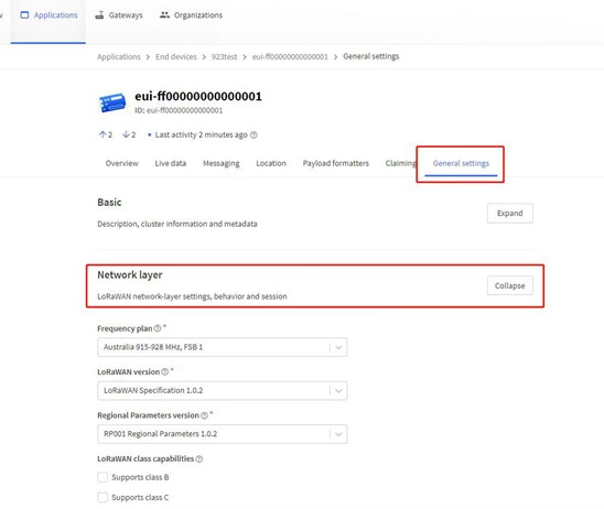
3.1 Gateway status
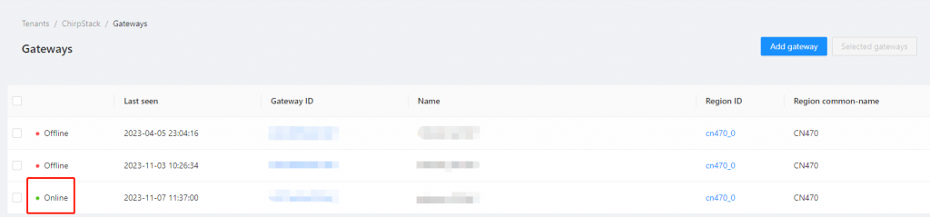
Go to the “Gateway” interface, in the gateway list, you can view the gateway connection status, Online indicates the gateway has successfully connected.
3.2 Add Device
Using a smoke sensor device as an example. For other devices, modify according to the actual parameters:
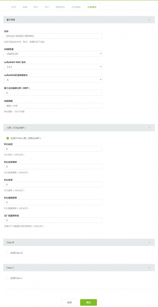
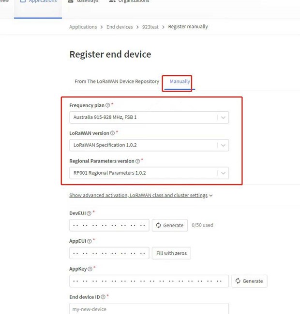
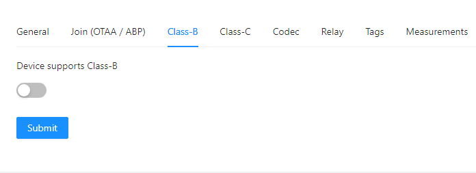
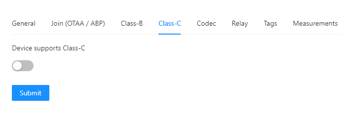
3.2.1 Create device profile
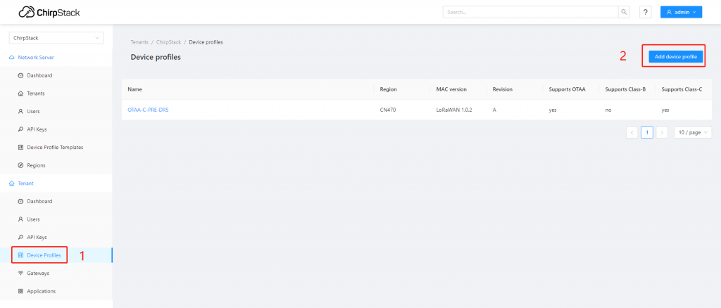
Go to “Device Profiles”, click “Add device profile” in the top right corner to add a device profile.
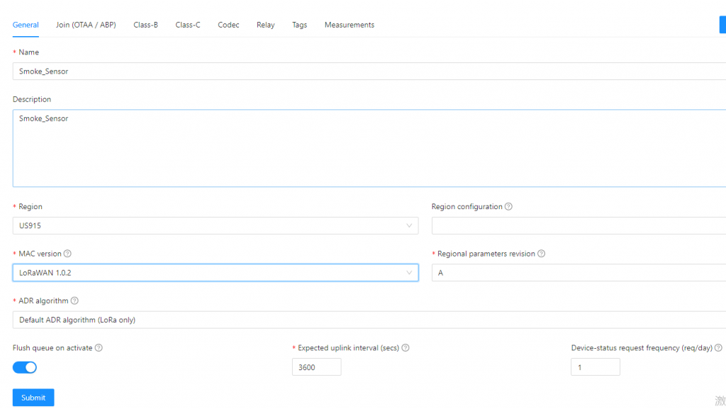
Description: Device profile description;
Region: US915;
MAC version: LoRaWAN 1.0.2;
Regional parameters revision: A;
ADR algorithm: Default ADR algorithm (LoRa only);
Join (OTAA/ABP): OTAA;
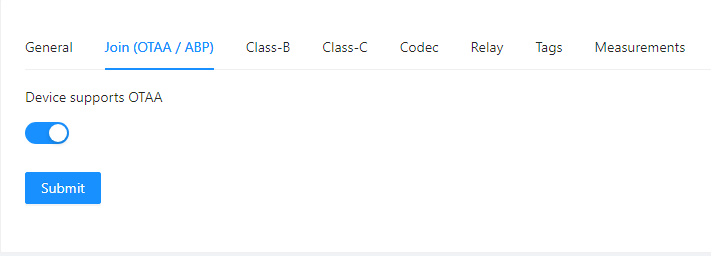
After filling in the device profile information, click “Submit”.
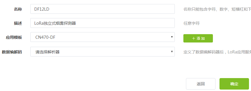
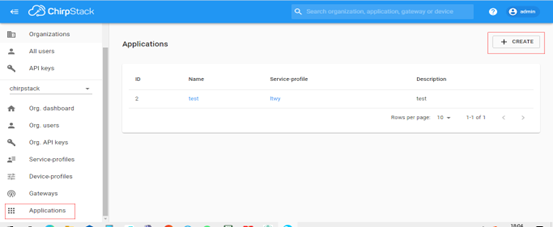
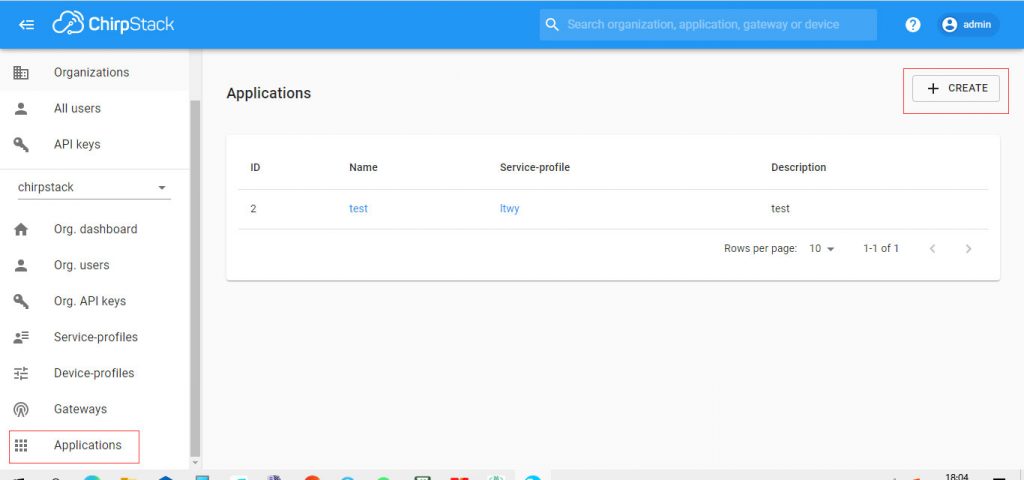
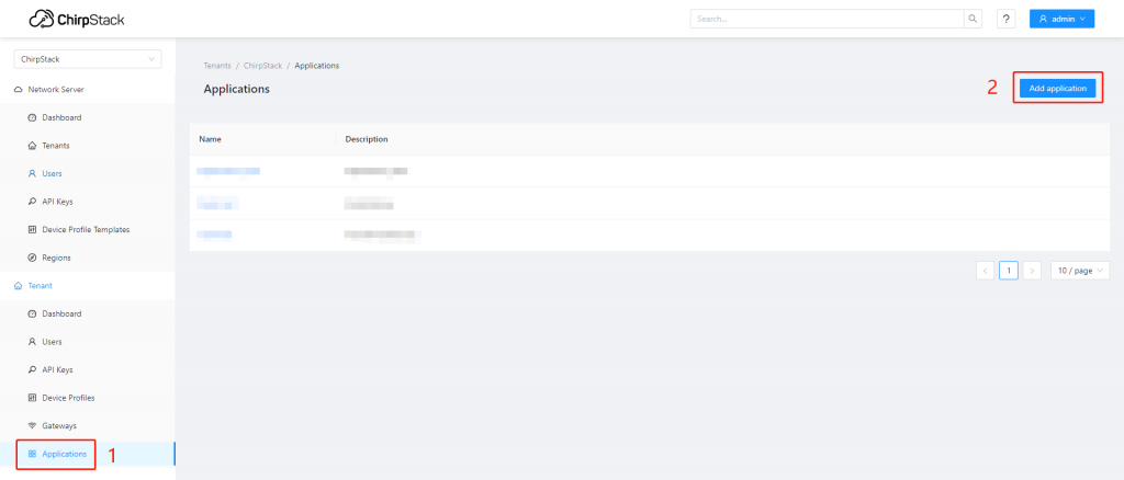
4. Add application
Go to “Application”, click “Add application” in the top right corner to add an application.
Description: Application description;
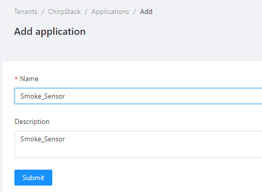
After filling in the application information, click “Submit”.
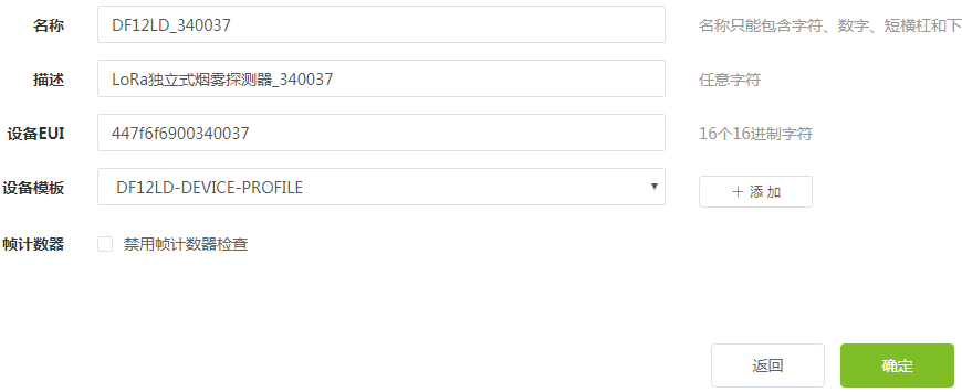
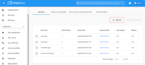
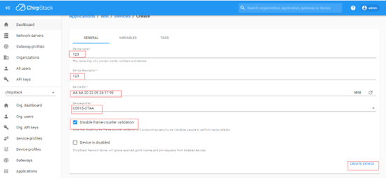
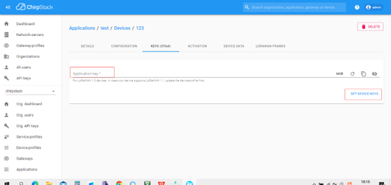
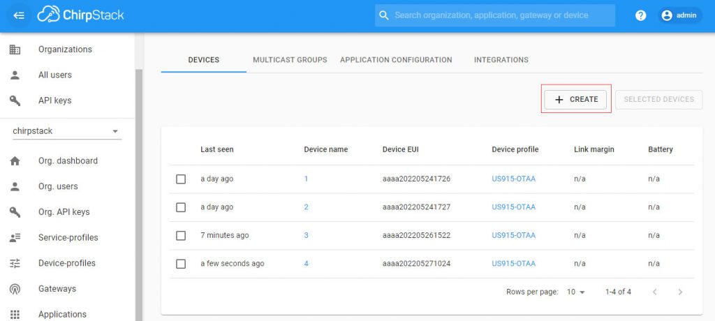
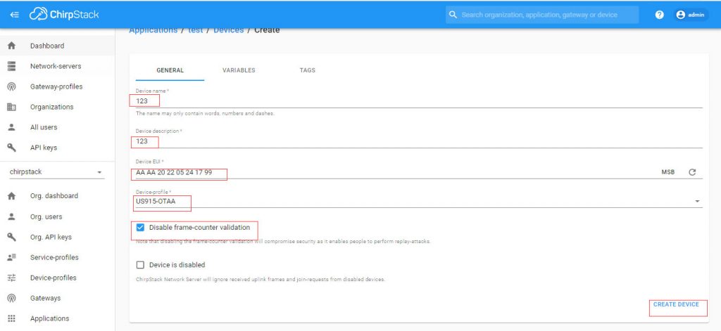
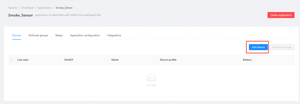
4.1 Add device
Go to “Application”, click on the application where you want to add a device, then click “Add device” to add a device.
Description: Device description;
Device EUI: Device DevEUI;
Join EUI: Device AppEUI;
Device profile: Select the newly created device profile above;
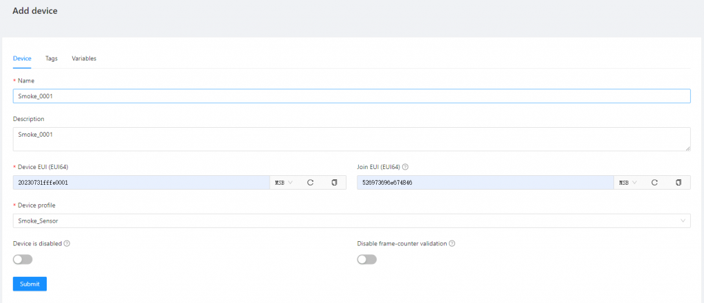
After filling in the device information, click “Submit”.
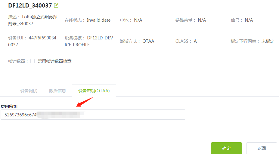
5. Check device status
Go to the ChirpStack interface, in “Dashboard”, check the device status. Active indicates the device has successfully joined the network.
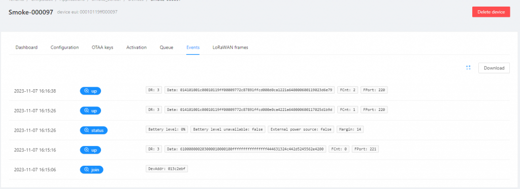
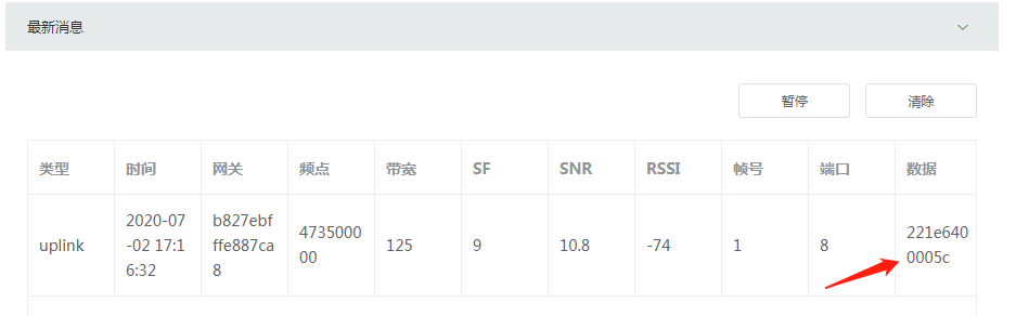
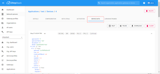
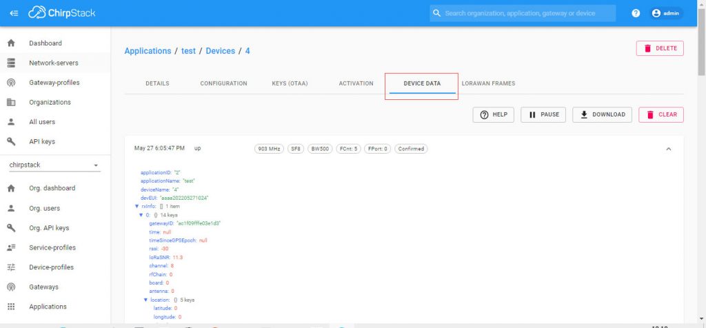
6. View device data
Go to “Applications”, select the corresponding device, and view the data flow in Events.