
For the first use, if it has been powered on, it can be used directly; if it has not been powered on, install the battery, plug the 2-core plug of the battery box into the battery socket (white) on the circuit board. Wait for the power indicator light to stay on, indicating that the program is running. If you need to reset the rotary switch again, please disconnect the power after setting (more than 1 minute to ensure that the microcontroller is completely reset or short-circuit the two short needles of the white socket on the main board) and then power on. At this time, users can install the sensor on site and put it into use. The wireless sensor should be placed as high as possible and in a relatively open space. It is recommended to be more than 1 meter above the ground; avoid placing metal objects around the sensor to avoid weakening the wireless signal; electronic interference may come from the following objects, so they should be avoided: generators, high current equipment, high voltage relays, transformers, etc.; vibration or impact may also be a source of interference, so the equipment should be kept stationary as much as possible during installation. Please do not install the equipment in an environment beyond the measurement range of the sensor, otherwise it may cause the product to malfunction and permanent damage to the sensor.
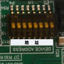
The method of setting the address with the rotary switch is as follows:
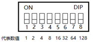
As shown in the figure, the rotary switch and the values represented by each bit, switch to “ON” is the valid value, switch to the opposite direction of “ON” is the invalid value, the address is the sum of the valid values. For example: if the address is 100, then the 3rd, 6th and 7th bits of the rotary switch are switched to the ON position, that is, 4+32+64=100.
Communication Protocol
| Register address | 0000H | 0001H | 0002H | 0003H | 0004H | 0005H | 0006H | 0007H | 0008H |
| Parameters | Temperature | Humidity | Spare | Spare | TVOC | CO2 | Spare | Spare | Spare |
| Unit | ℃ | %RH | PPM | PPM | |||||
| Range | -40-80 | 0-100 | 0-50 | 0-5000 | |||||
| Sample Value | /10 | /10 | /10 | /1 | |||||
| Operation | Read only | Read only | Read only | Read only |
| Parameters | 0009H | 000AH | 000BH | 000CH | 000DH | 000EH | 000FH | ||
| Parameters | Spare | Spare | Spare | Spare | Battery voltage | Online sign | signal strength | ||
| Unit | |||||||||
| Range | |||||||||
| Sample Value | |||||||||
| Operation |
Connect to Dragino gateway and ChirpStack
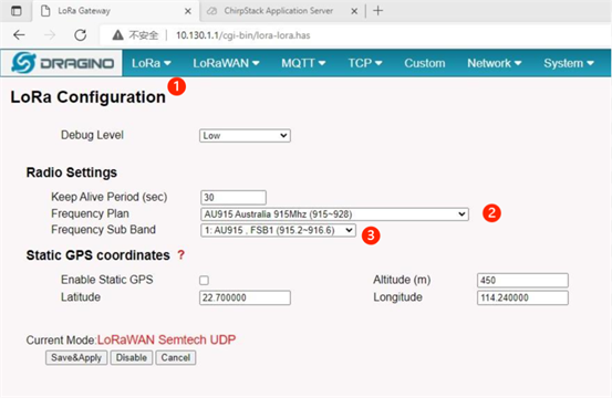
Connect via LAN port with direct connection from PC ,Power on the gateway, access the gateway with the url( 10.130.1.1) in the browser( Access via WiFi AP network http:// IP_ADDRESS:8000 ), click LORA, and select correct frequency plan and frequency band mask. The default frequency band mask is: 1 . click Save & Apply
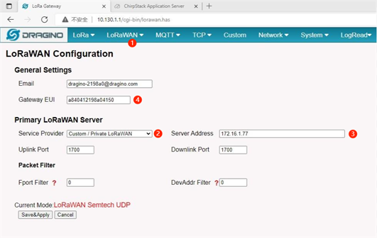
Select the LORANWAN configuration interface to set the NS address of the gateway. We use The CHIRPSTACK server as example for the test, so select CUSTOM and select it according to the real server address. Record the GATEWAY EUI information. click Save & Apply.
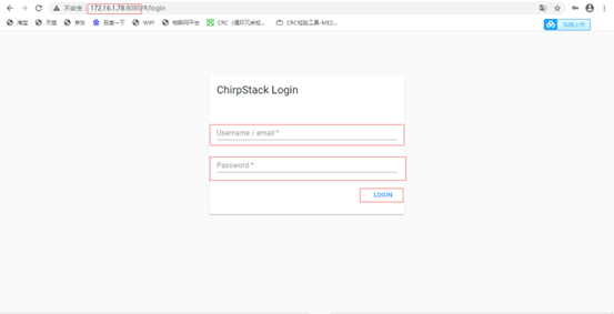
Log in to the ChirpStack server Enter the IP address and port, enter the user name and password, and click Login.
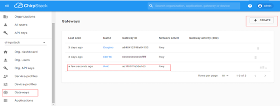
Add a LORAWAN gateway. Click Gateways and CREATE to enter the gateway EUI, which is the gateway EUI shown in the pictures below.
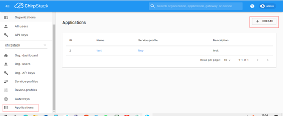
Add an app Click Applications and click CREATE to add an app
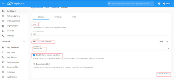
Click Add Application, add device, click CREATE to add device name.
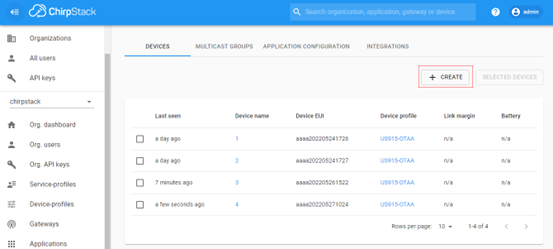
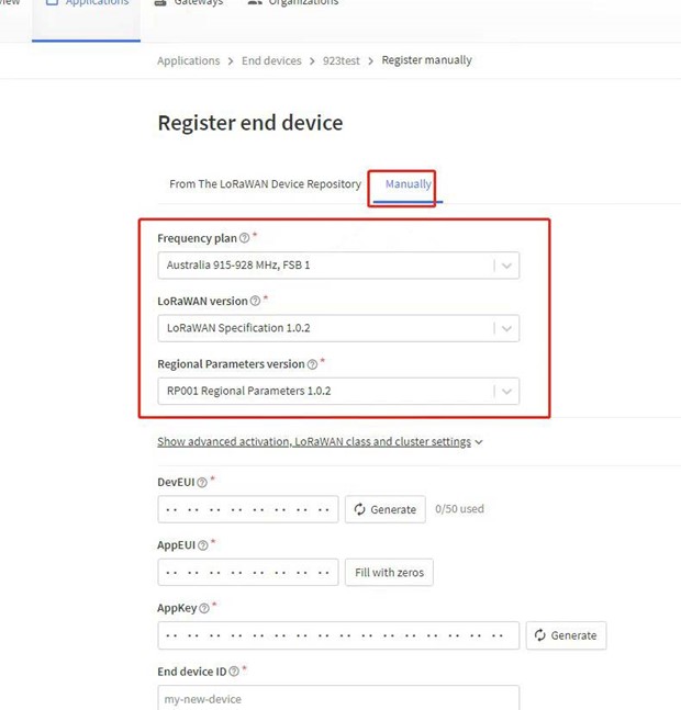
Device Description DEVEUI of device, select the corresponding frequency band, and click Add Device, as shown in picture below. AU915 communication is not very stable, which may be related to the frequency band. It is recommended to disable the frame count verification function.
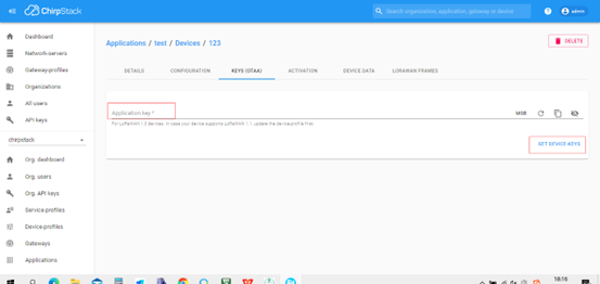
Add APPKEY, enter APPKEY parameter in Application Key, and click SET device-keys.
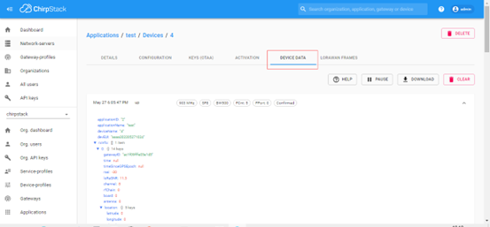
Click DEVICE DATA to view the DATA
DECODE Example
function Decode(fPort, bytes, variables) {
var paramLength = bytes[2]/2;
var params = new Object();
for(var i=0;i<paramLength;i++)
{
params[“param”+i] = bytes[3+i2]256+bytes[4+i*2];
}
return params;
}
DECODER
function decodeUplink(input) {
var params = new Object();
params[“Temp”] =
input.bytes[3]256+input.bytes[4]
params[“Humi”] = input.bytes[5]256+input.bytes[6]
params[“PM2.5”] =
input.bytes[7]256+input.bytes[8]
params[“TVOC”] = input.bytes[11]256+input.bytes[12]
params[“CO2”] = input.bytes[13]256+input.bytes[14]
params[“O3”] = input.bytes[17]256+input.bytes[18]
params[“HCHO”] = input.bytes[11]256+input.bytes[22]
return {
data: params
};
}
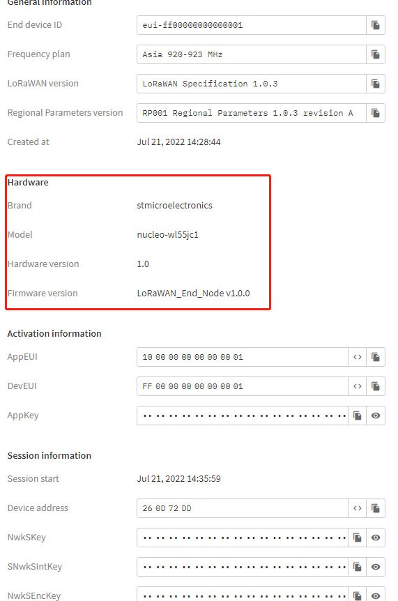
TTN Device Hardware options
Brand: stmicroelectronics Model: nucleo-wl55jc1 Hardware version: 1.0 Firmware version: 1.0
TTN Decoder
function decodeUplink(input) {
var params = new Object();
params[“Temp”] =
input.bytes[3]256+input.bytes[4]
params[“Humi”] = input.bytes[5]256+input.bytes[6]
params[“PM2.5”] =
input.bytes[7]256+input.bytes[8]
params[“TVOC”] = input.bytes[11]256+input.bytes[12]
params[“CO2”] = input.bytes[13]256+input.bytes[14]
params[“O3”] = input.bytes[17]256+input.bytes[18]
params[“HCHO”] = input.bytes[11]256+input.bytes[22]
return {
data: params
};
}