1.AT Command
1.1Command List
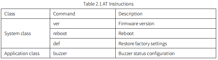
The list of AT instructions related to the device is as follows:
1.2 Command Format
The command uses ASCII code string, there are 3 formats, they are as follows:
1. Execution format: at+<command><CR>; 2. Query format: at+<command>=?<CR>; 3. Configuration format: at+<command>=<parameter1>[,parameter2]…[,parametern]<CR>.
Each command supports at least one type. Format description:
1. The command starts with “at+” and ends with<CR>(carriage return, hexadecimal value is 0x0D, which is represented by ‘ r’ in C language); 2. If the end of the command (or in the command) contains a newline character (<LF>),<LF>is ignored; 3.<>: indicates the part that must be included; 4. []: indicates an optional part; 5. Commands and parameters are not case sensitive.
The return format of command execution varies depending on the command, and there are mainly the following types of formats:
1. <ok><CR><LF>, indicating success, more common in the return of configuration commands; 2. <error,1><CR><LF>, indicating that the input command cannot be recognized; 3. <error,2><CR><LF>, indicating that the command can be recognized, but the input parameter is invalid, which is more common in the return of configuration commands; 4. <parameter1>[,<parameter2>,…<parametern>]<CR><LF>, which is more common in the return of query commands; 5. Other forms, which vary from command to command, are more common in the return of execution-type commands. Where <CR> is the carriage return character and <LF> is the line feed character (0x0A in hexadecimal, represented by ‘\n’ in C language).
1.3 Command Reply
1.3.1 Success
After executing the command, if the return is successful, return ok\r\n.
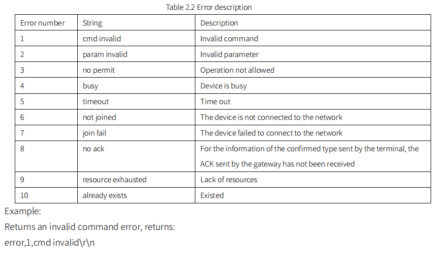
1.3.2 Error
After executing the command, if an error is returned, it has the following format: error,<error number>,[error description string]\r\n Among them, the error number and error description string are shown in the following table:
1.4 System Commands
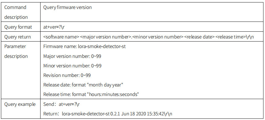
1.4.1 ver
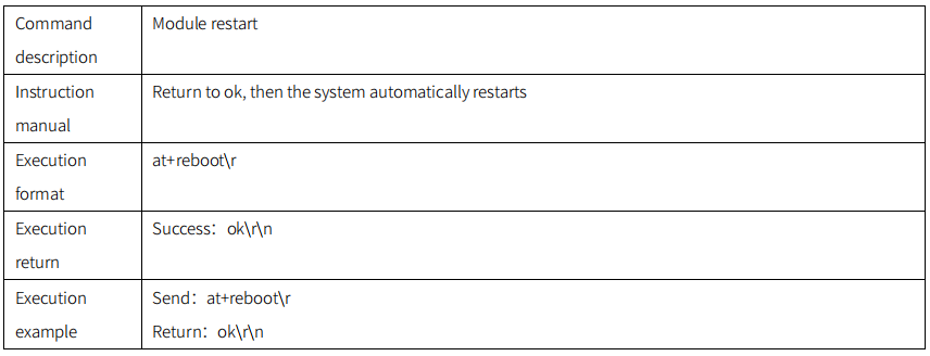
1.4.2 reboot
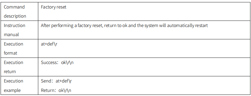
1.4.3 def

1.5 Application Commands
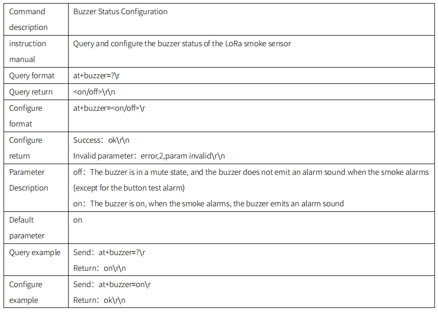
1.5.1 buzzer
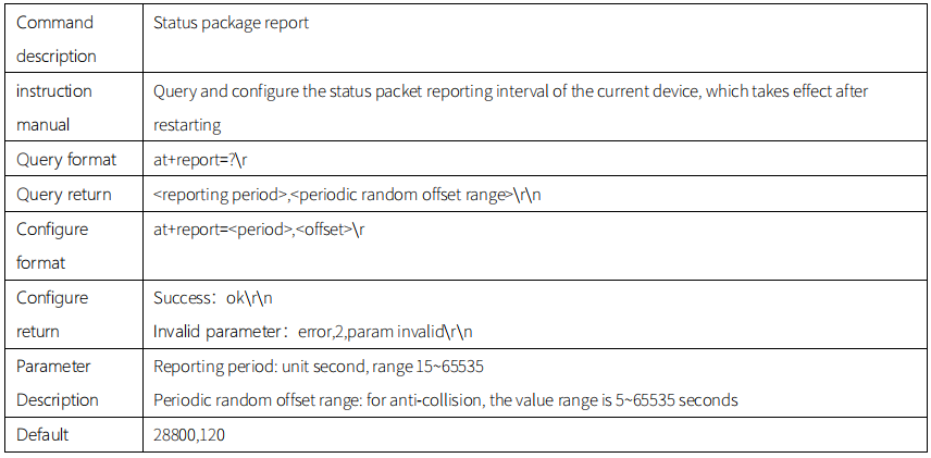
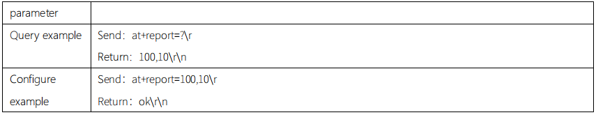
1.5.2 report
Communication Protocol
1.1 Periodic reporting
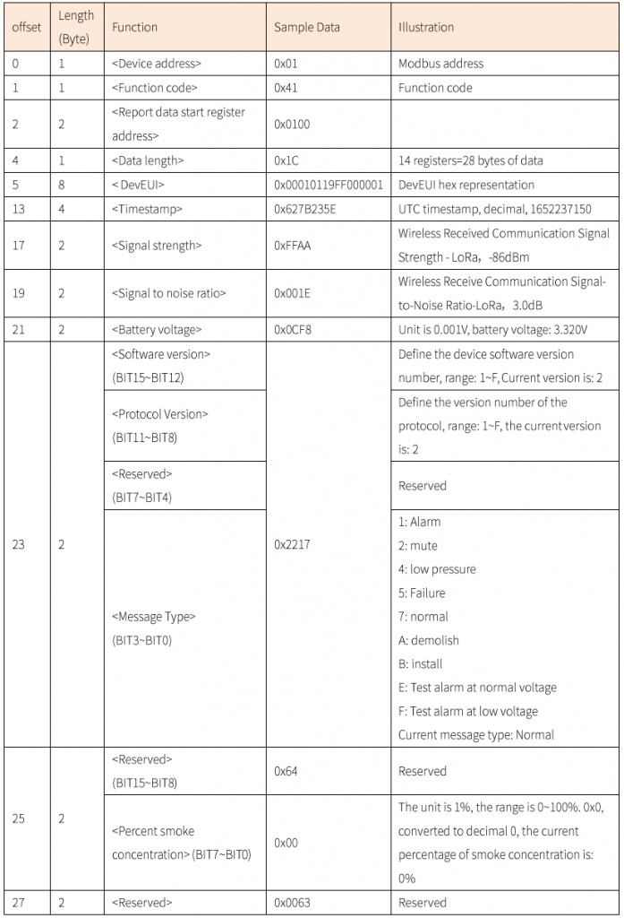
The status reporting period defaults to 8h/packet :
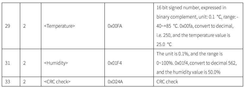
FA 01 F4 D2 4A
Data Analysis: Device DevEUI: 00010119FF000001; UTC Timestamp: 1652237150; Signal Strength: -86dBm;
Signal-to-Noise Ratio: 3.0dB; Battery Voltage: 3.32V; Software Version: 2, Protocol Version: 2; Message Type:
Normal; Smoke Concentration Percentage: 0%; Temperature: 25.0℃; Humidity: 50.0%; CRC Check: 0xd24a
1.2 Cancel the alarm report
When the device detects that the smoke concentration is 100%, the device will trigger an alarm and report at a high frequency of 10s/packet. Users can cancel the smoke alarm through the following ModBus commands. Disarm the alarm report and only stop the high-frequency report of 10s/packet .
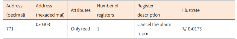
write to the register.
Example of Canceling the alarm report: 01 10 03 03 00 01 02 01 73 d5 16
Device Debugging
1.3 LoRaWAN NS
The following LoRaWAN NS operations only show the general operation process
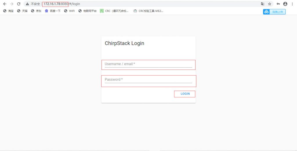
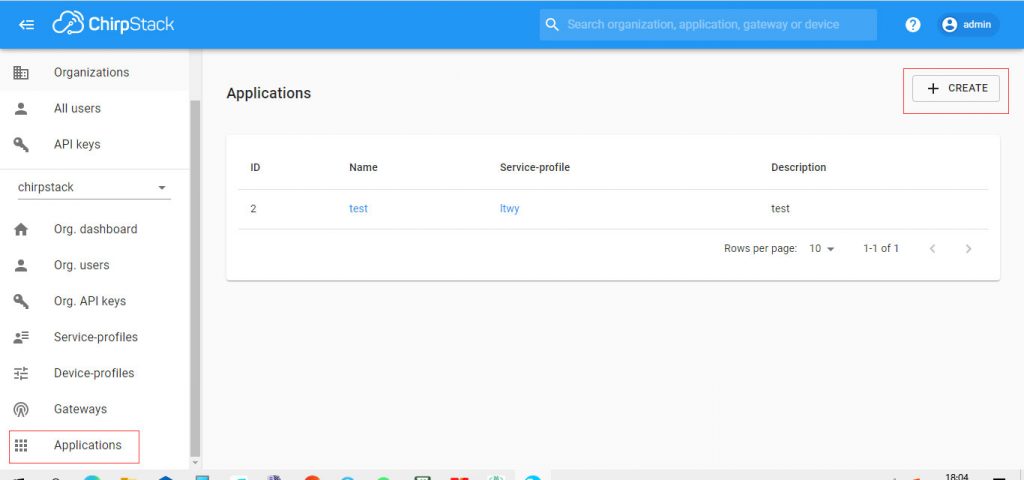
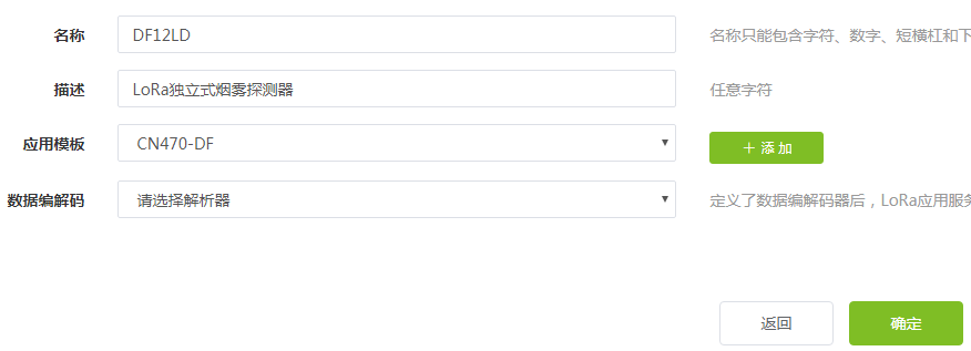
1.3.1 Create an application
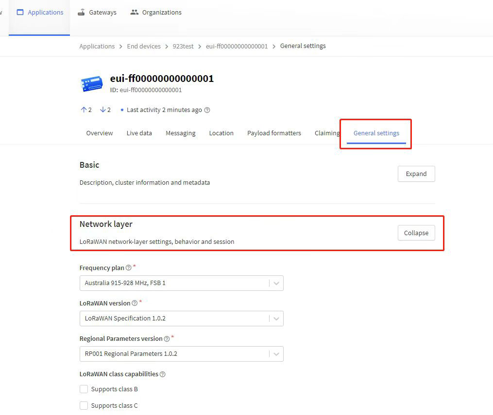
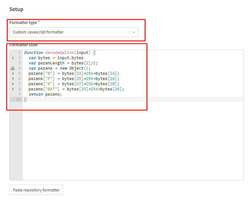
After logging into the platform, create a LoRa smoke sensor application. Note: Select “Please select a parser” for “Data codec”, do not select other options.
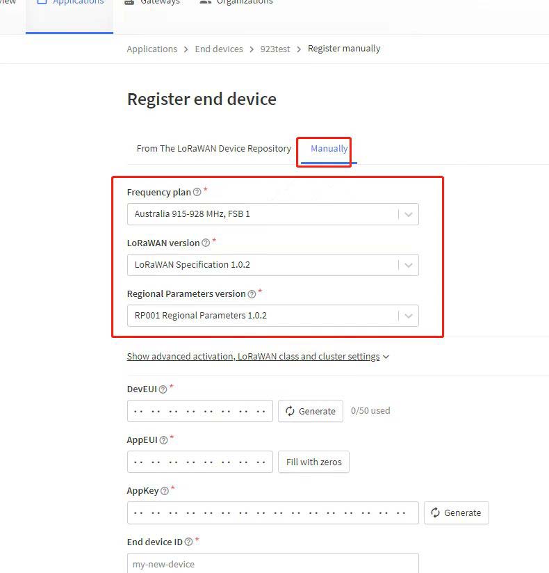
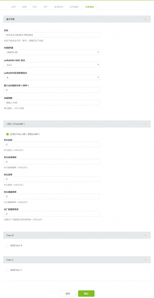
1.3.2 Creating a Device Template
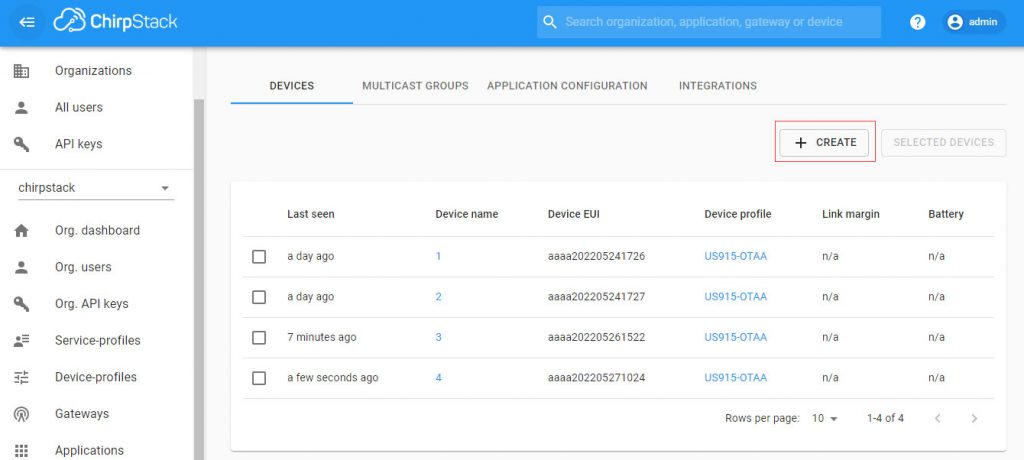
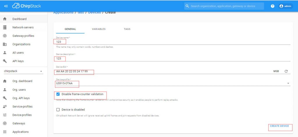
1.3.3 Registering the device
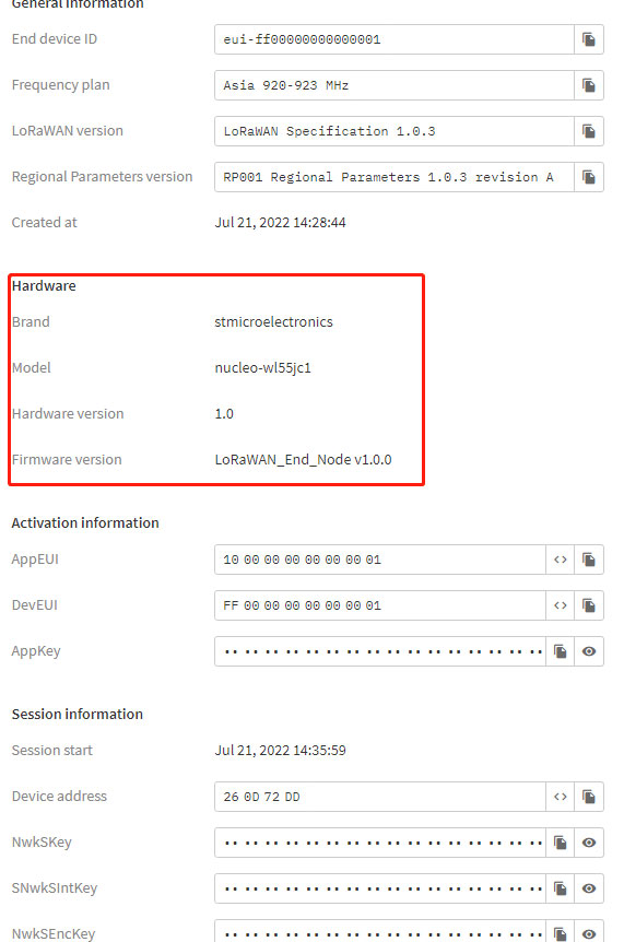
As shown in the figure below, create a device, paste DevEUI on the back of the device, and remove the hanging plate to see it.
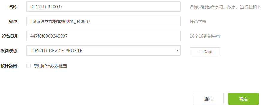
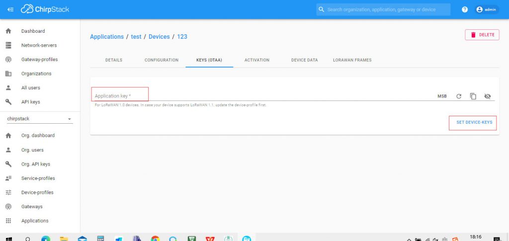
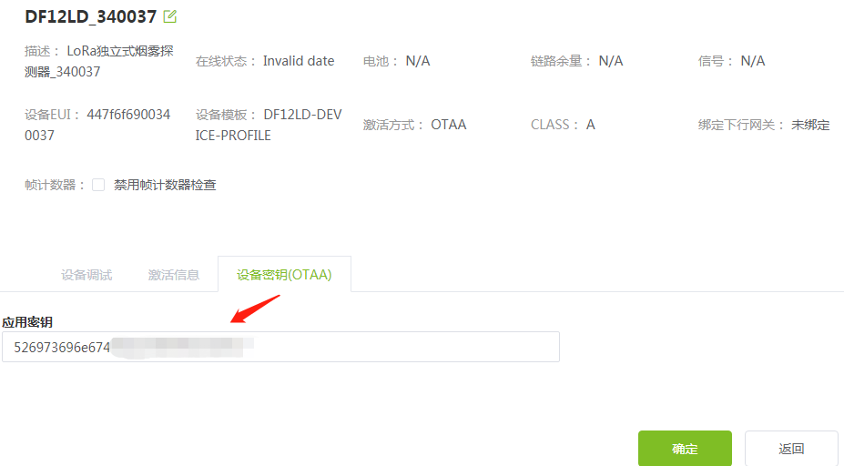
As shown in the figure below, after creating the device, you need to fill in the device key (AppKey, shipped
with the product)
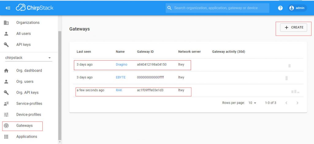
1.4 Gateway
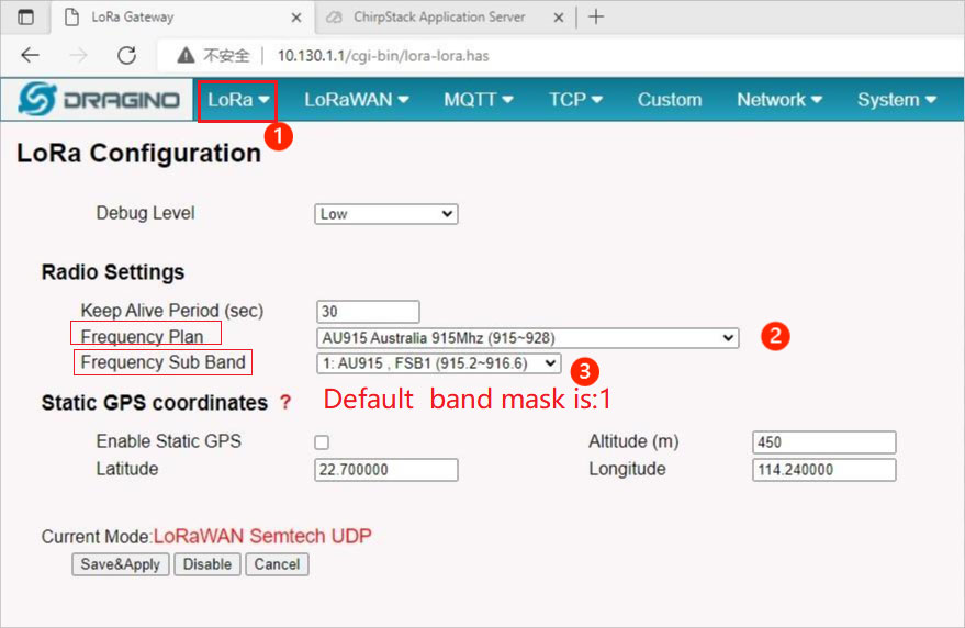
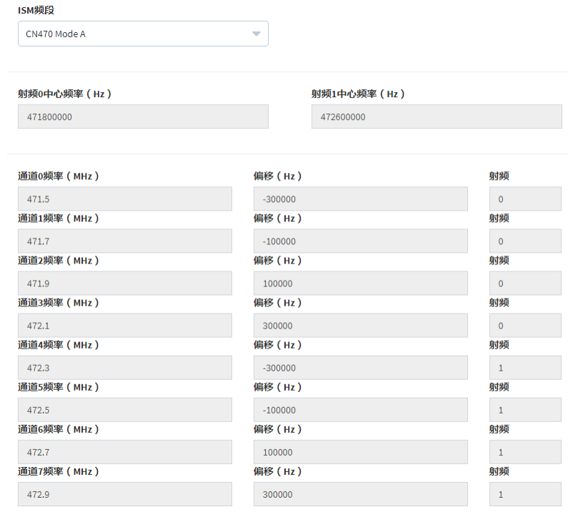
1.4.1 LoRa RF
Log in to the web management page of the gateway and configure the LoRa radio as shown in the figure below. The figure below shows the configuration of CN470 as an example.
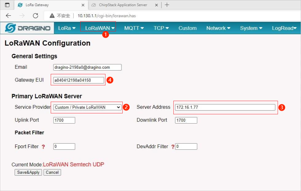
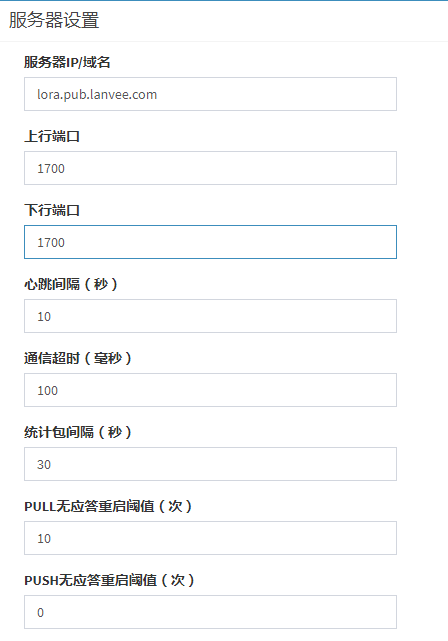
1.4.2 LoRa Server
As shown in the figure below, configure the LoRa server.
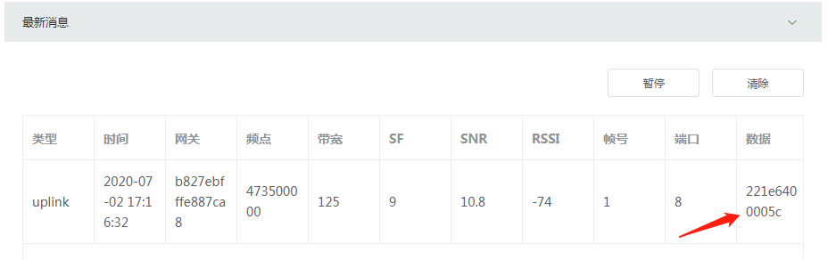
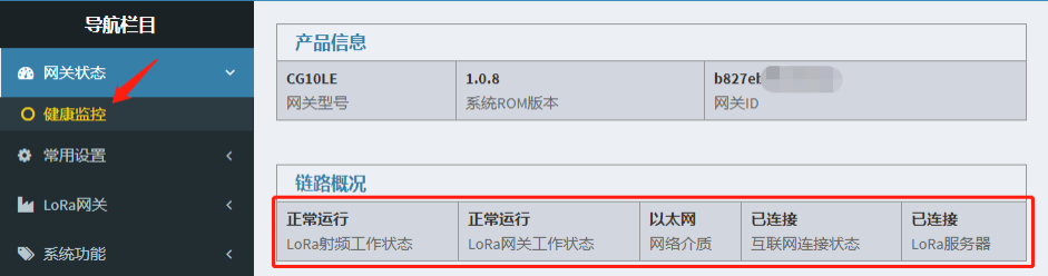
After the above configuration is complete, make sure that the gateway is working normally, as shown in the following figure.
1.5Device
1.5.1Connect Network
The following operations can trigger the device to join the network: 1. Power on the device again. 2. If the device is not connected to the network, press and hold the button for 3s and then release it, and the device will access the network once. The device is successfully connected to the network, and the red LED is always on for 5s. The network connection fails, and the red LED flashes slowly for 5s.
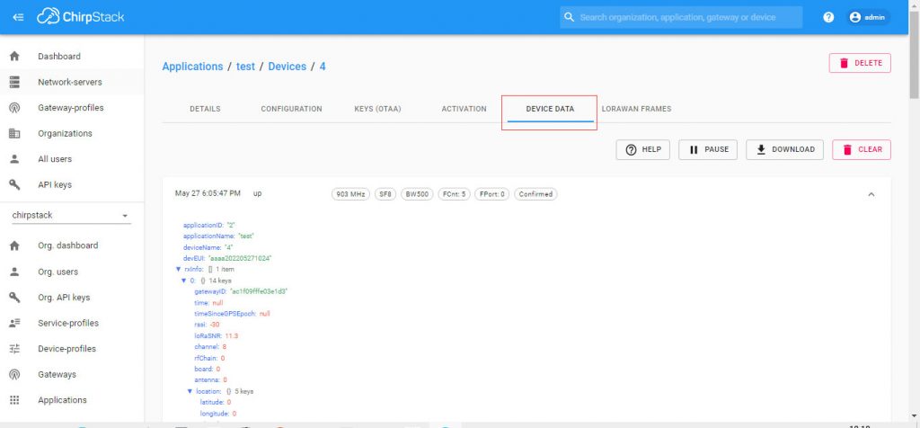
1.5.2 Test Alarm
After the device is successfully connected to the network, the alarm test can be performed. Press and hold the button for 3s and release it. During the press and hold, the device will emit sound and light alarms. After releasing, the device will report the test alarm data to the platform through LoRaWAN. As shown in the figure below, please refer to Chapter III for data analysis.