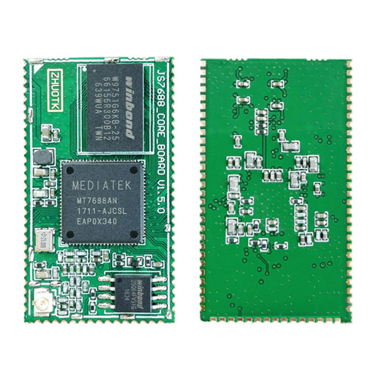
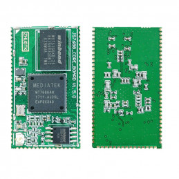
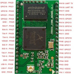
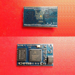
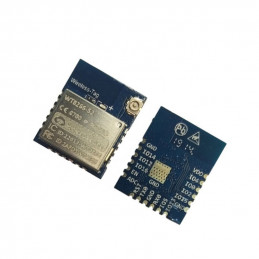
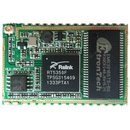
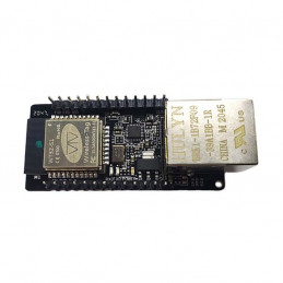
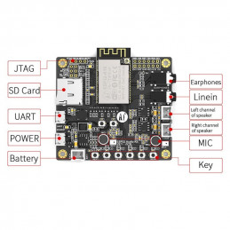
DWM-JS7688 The core board module is a wifi module based on the MTK (Mediatch) MT7688AN SOC chip CPU, frequency of 580 MHz, onboard optional 64MB DDR2 RAM / 8MB flash, 128MB DDR2 RAM / 16MB flash, 256MB DDR2 RAM / 32MB flash three configuration options,150MB wifi, external lead out USB 2.0 Host, GPIO, UART, I2S, I2C, SD card interface, SPI, PWM, Ethernet interface, wifi antenna interface, etc. This module has a small volume, low power consumption, small heat value, and stable wifi and network port transmission performance. Running the OpenWRT (Linux) system for long-term stable operation.
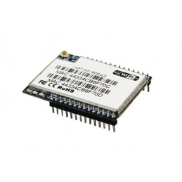
The peripheral circuit of the module is very simple, only adding a 3.3V DC power supply to start the system, and can be controlled by WIFI. Using a gold-plated pin interface or stamp hole interface can be very stable and fixed on the bottom plate. It can be used for smart homes, IP cameras, VOIP, remote control shooting aircraft, remote monitoring systems, portable 4G routers, audio intercoms, simple WEB network servers, simple FTP servers, remote downloads, remote control vision cars, and other super applications.
Features:
| Product Name |
DWM-JS7688 Core board |
| Support Operating system |
Openwrt(Linux) |
| Processor |
MT7688AN MIPS 24KEc |
| System Frequency |
580MHz |
| Memory |
64MB/128MB/256MB DDR2 RAM |
| Flash |
8MB/16MB/32MB Nor flash |
| Ethernet port |
5xWAN / LAN 10 / 100M adaptive |
| USB interface |
1xUSB 2.0 host |
| PCIE interface |
1xPCIE |
| UART serial port |
UART0 (used as default debugging)、UART1、UART2 |
| GPIO |
total 40 (reuse with other functions) |
| I2S |
1xI2S, Support VOIP application |
| I2C |
1xI2C |
| SPI master |
2xSPI (one SPI is occupied by flash, Another SPI Reserved) |
| SPI slave |
1xSPI |
| PWM |
4xPWM |
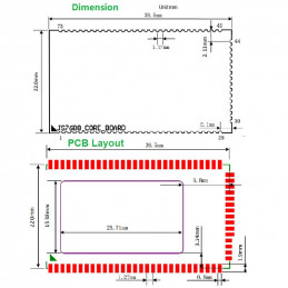
| Dimension |
38.5mm x 22mm x 2.8mm |
| Working voltage |
3.3V ±10% |
| Power consumption |
0.6W |
| Current requirements |
Over 500mA |
| Antenna interface |
1 x IPEX |
| working temperature |
-20~60℃ |
| wireless protocol |
IEEE802.11 b/g/n |
| wireless Data Rate |
1T1R,Maximum 150Mbps |
| RF Power Output |
Maximum 18dbm |
| Transmission distance |
100 meters(Open area) |
| Working mode |
routing, AP, relay, bridge |
Pin Definition
| Pin |
Function 0 |
Function 1 |
Function 2 |
Function 3 |
Note |
| 1 |
GND |
N/A |
N/A |
N/A |
Main Power Ground |
| 2 |
GND |
N/A |
N/A |
N/A |
Main Power Ground |
| 3 |
GND |
N/A |
N/A |
N/A |
Main Power Ground |
| 4 |
VDD3V3 |
N/A |
N/A |
N/A |
Main Power DC 3.3V Input |
| 5 |
VDD3V3 |
N/A |
N/A |
N/A |
Main Power DC 3.3V Input |
| 6 |
VDD3V3 |
N/A |
N/A |
N/A |
Main Power DC 3.3V Input |
| 7 |
REF_CLK_0 |
GPI037 |
N/A |
N/A |
Default as GPI0
SYSTEM_LED |
8 |
WDT_RST_N |
GPI038 |
N/A |
N/A |
Default as GPI0
RESET_FN_KEY |
| 9 |
EPHY_LED4_N JTRST_N |
GPIO39 |
w utif n[6] |
jtrstn_n |
Default as GPI0
USER_KEY2 |
| 10 |
EPHY_LED3_N JTCLK |
GPI040 |
w_utif n[7] |
jtclk_n |
Default as GPI0
USER_KEY1 |
| 11 |
EPHY_LED2_NJTMS |
GPI041 |
w_utif n[8] |
jtms_n |
Default as Ethernet Port 2 hardware
indicator light |
12 |
EPHY_LED1 N JTDI |
GPI042 |
w_utif n[9] |
jtdi_n |
Default as Ethernet Port 1 hardware
indicator light |
| 13 |
EPHY_LEDO N JTDO |
GPI043 |
N/A |
jtdo_n |
Default as Ethernet Port 0 hardware
indicator light |
| 14 |
WLED_N |
GPI044 |
N/A |
N/A |
Default as GPIO, serving as wireless operation indicator light |
| 15 |
GND |
N/A |
N/A |
N/A |
GND |
16 |
UART_TXD1 |
GPI045 |
PWM_CHO |
antsel[1] |
Internally connected to 10K pull-up resistor to 3.3V, default as UART_TXD1 |
| 17 |
UART_RXD1 |
GPI046 |
PWM_CH1 |
antsel[O] |
Default as UART_RXD1 |
| 18 |
I2S_SDI |
GPI00 |
PCMDRX |
antsel[5] |
Default as I2S_SDI |
19 |
I2S_SDO |
GPI01 |
PCMDTX |
antsel[4] |
Internally connected to 10K pull-down resistor to ground, default as I2S_SDO |
| 20 |
I2S_WS |
GPIO2 |
PCMCLK |
antsel[3] |
Default as I2S_WS |
| 21 |
I2S_CLK |
GPIO3 |
PCMFS |
antsel[2] |
Default as I2S_CLK |
| 22 |
I2C_SCLK |
GPIO4 |
sutif_txd |
ext_bgclk |
Default as I2C_SCLK |
| 23 |
I2C_SD |
GPI05 |
sutif_rxd |
N/A |
Default as I2C_SD |
| 24 |
SPI_CS1 |
GPI06 |
REF_CLK_O |
N/A |
Internally connected to 10K pull-down resistor to ground, default as SPI_CS1 |
25 |
VDD3V3_PROG |
N/A |
N/A |
N/A |
External flash programmer power DC 3.3V input pin. Note: Only needed when connecting an external flash programmer, normally left floating |
| 26 |
SPI_CLK |
GPI07 |
N/A |
N/A |
Internally connected to 10K pull-up resistor to 3.3V, default as SPI_CLK |
| 27 |
GND |
N/A |
N/A |
N/A |
GND |
| 28 |
SPI_MOSI |
GPI08 |
N/A |
N/A |
Internally connected to 10K pull-down resistor to ground, default as SPI_MOSI |
| 29 |
SPI_MISO |
GPI09 |
N/A |
N/A |
Default as SPI_MISO |
| 30 |
GPI011 |
GPI011 |
REF_CLK_0 |
PERST_N |
Default as REF_CLK_O |
31 |
SPI_CSO |
GPI010 |
N/A |
N/A |
Default as SPI_CSO, used by the system SPI flash, available for flash programming |
32 |
UART_RXDO |
GPI013 |
N/A |
N/A |
Default as UART_RXDO, system debugging serial port |
33 |
UART_TXDO |
GPI012 |
N/A |
N/A |
Internally connected to 10K pull-down resistor to ground, default as UART_TXDO, system debugging serial port |
34 |
MDI_R_PO_P |
N/A |
N/A |
N/A |
Ethernet Port 0 receive positive terminal |
| 35 |
GND |
N/A |
N/A |
N/A |
GND |
| 36 |
GND |
N/A |
N/A |
N/A |
GND |
| 37 |
MDI_R_PO_N |
N/A |
N/A |
N/A |
Ethernet Port 0 receives negative terminal |
| 38 |
MDI_T_PO_N |
N/A |
N/A |
N/A |
Ethernet Port 0 transmit negative terminal |
| 39 |
MDI_T_PO_P |
N/A |
N/A |
N/A |
Ethernet Port 0 transmit positive terminal |
|
IOT Gateway Work Mode |
IoT device Work Mode |
| 40 |
MDI_T_P1_N |
SPIS_CLK |
GPI015 |
w_utif[1] |
PWM_CH1 |
PWM_CH1 |
| 41 |
MDI_T_P1_P |
SPIS_CS |
GPI014 |
w utif[0] |
PWM_CHO |
PWM_CHO |
| 42 |
MDI_R_P1_N |
SPIS_MOSI |
GPI017 |
w utif[3] |
UART_RXD2 |
Default as UART_RXD2 |
| 43 |
MDI_R_P1_P |
SPIS_MISO |
GPI016 |
w_utif[2] |
UART_TXD2 |
Default as UART_TXD2 |
| 44 |
MDI_R_P2_N |
PWM_CH1 |
GPI019 |
w_utif[5] |
SD_D6 |
Default as GPIO |
| 45 |
MDI_R_P2_P |
PWM_CHO |
GPI018 |
w utif[4] |
SD_D7 |
Default as GPI0 |
| 46 |
GND |
N/A |
N/A |
N/A |
GND |
| 47 |
MDI_T_P2_P |
UART_TXD2 |
GPI020 |
PWM_CH2 |
SD_D5 |
PWM_CH2 |
| 48 |
MDI_T_P2_N |
UART_RXD2 |
GPIO21 |
PWM_CH3 |
SD_D4 |
PWM_CH3 |
| 49 |
MDI_T_P3_P |
SD_WP |
GPI022 |
w_utif[10] |
w_dbgin |
Default as SD_WP |
| 50 |
MDI_T_P3_N |
SD_CD |
GPIO23 |
w_utif[11] |
w_dbgack |
Default as SD_CD |
| 51 |
GND |
N/A |
N/A |
N/A |
GND |
| 52 |
MDI_R_P3_N |
SD_DO |
GPI025 |
w_utif[13] |
W_jtdi |
Default as SD_DO |
| 53 |
MDI_R_P3_P |
SD_D1 |
GPI024 |
w_utif[12] |
w_jtclk |
Default as SD_D1 |
| 54 |
GND |
N/A |
N/A |
N/A |
GND |
| 55 |
MDI_R_P4_P |
SD_CLK |
GPI026 |
w_utif[14] |
w_jtdo |
Default as SD_CLK |
| 56 |
MDI_R_P4_N |
SD_CMD |
GPI027 |
w_utif[15] |
dbg_uart_t |
Default as SD_CMD |
| 57 |
MDI_T_P4_P |
SD_D3 |
GPIO28 |
w_utif[16] |
w_jtms |
Default as SD_D3 |
| 58 |
MDI_T_P4_N |
SD_D2 |
GPI029 |
w_utif[17] |
w_jtrst_n |
Default as SD_D2 |
| 59 |
GND |
N/A |
N/A |
N/A |
GND |
| 60 |
USB_N |
N/A |
N/A |
N/A |
USB- |
| 61 |
USB_P |
N/A |
N/A |
N/A |
USB+ |
Package Include
Module: DWM-JS7688 core module (If a DIP test board required just leave a message or send an email to sales@dwmzone.com)
EVB kit:1x EVB kit board, 1x DWM-JS7688 core module with DIP test board,1x 2.4GHz antenna.