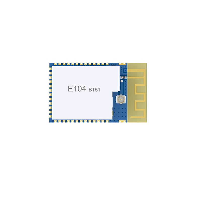
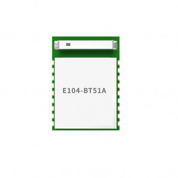
E104-BT51A is a serial port to BLE Bluetooth slave node module that supports Bluetooth protocol version 5.0. It is small in size and low in power consumption. It works in the 2.4GHz frequency band. The E104-BT51A module is a serial-to-BLE Bluetooth module which is based on TI's CC2640R2F chip. The module uses AT commands to set parameters, simple operation and convenient configuration. The module only supports Bluetooth slave mode. The module functionally supports low-power broadcast with
changeable content, variable baud rate data transparent transmission and file transmission, support for air command configuration, IO
port switch level setting, frequency And cycle variable PWM output, support AD analog quantity acquisition, Bluetooth battery
voltage service. Modules can be widely used in smart wear, home automation, home security, personal health care, smart home
appliances, accessories and remote controls, automotive electronics, lighting industry, industrial Internet, smart data collection, smart control and other fields. The module supports the maximum baud rate of 921600bps and the 2M PHY air rate of Bluetooth 5.0.
Features
Support Bluetooth BLE 5.0 protocol;
Supports adjustable Bluetooth package length;
Support two working modes of configuration and transparent transmission;
Support automatic broadcast and automatic connection after startup;
Support IBeacon and ordinary broadcast switching;
Support broadcast data can be set;
Support MAC address binding;
Support multiple serial port modes and baud rate;
Support custom 16-bit UUID and 128-bit UUID;
Support Bluetooth parameter air configuration;
The maximum communication distance is 75m(0dBm);
Support ultra-low power consumption sleep mode, and synchronously broadcast data and maintain connection;
Support IO port level output;
Support PWM output with variable frequency period;
Support ADC analog quantity acquisition;
Support battery voltage detection service;
Support 2M, 1M airspeed;
The maximum value of MTU data transmission unit is 230 bytes;
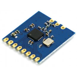
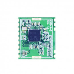
Built-in PCB antenna, no external antenna is required;
Applications
Wireless meter reading wireless sensor
Smart home
Industrial remote control, telemetry
Smart buildings, smart buildings
Automatic data collection
Health sensor
Smart wearable devices
Smart robot
Wireless sensing
Electronic label
Intelligent control
Parameters
| RF Parameter |
Value |
Remark |
| Frequency [MHz] |
2402~2480 MHz |
ISM band |
| Transmitting power |
5 dBm |
- |
| Receiving sensitivity [dBm] |
-99 dBm |
Air rate is 250k bps |
| Distance |
75m(0dBm) |
Clear and open environment, height 1.5m (only 75m can be tested by the host) |
| Hardware Parameter |
Value |
Remark |
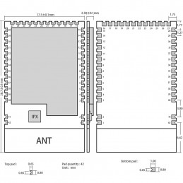
| Size |
17.5*28.7 mm |
- |
| Antenna |
PCB |
50Ω Impedance |
| Communication interface |
UART |
- |
| Package |
SMD |
- |
| Electronic parameter |
Min |
Typ |
Max |
Unit |
Remarks |
| Voltage supply [V] |
1.8 |
3.3 |
3.6 |
V |
≥3.3 V ensures output power |
| Communication level [V] |
- |
3.0 |
- |
V |
For 5V TTL, it may be at risk of burning down |
| Sleep broadcasting current(default) |
- |
29.93 |
- |
uA |
Broadcast interval is 1s |
| Wake-up broadcasting current(default) |
- |
1581 |
- |
uA |
Broadcast interval is 1s |
| Wake-up no broadcasting current(default) |
- |
1570 |
- |
uA |
- |
| wake-up connection current(default) |
- |
2301 |
- |
uA |
Connection interval is 1s |
| Sleep connection current(Default) |
- |
259.1 |
- |
uA |
Connection interval is 1s |
| Operating temperature [℃] |
-40 |
- |
+85 |
℃ |
- |
Pin Definition(See the picture)
| Pin No. |
Name |
Direction |
Function |
| 1、2、3 |
GND |
- |
Ground, connected to power supply reference ground |
| 4 |
DIO_0 |
Input/Output |
General IO port, sensor controller (see CC26xx manual for details) reserved |
| 5 |
DIO_1 |
Input/Output |
General IO port, sensor controller (see CC26xx manual for details) reserved |
| 6 |
DIO_2 |
Input |
RX |
| 7 |
DIO_3 |
Output |
TX |
| 8 |
DIO_4 |
Input/Output |
OUTGPIO0 |
| 9 |
DIO_5 |
Input/Output |
OUTGPIO1 |
| 10 |
DIO_6 |
Input/Output |
OUTGPIO2 |
| 11 |
DIO_7 |
Input/Output |
OUTGPIO3 |
| 12 |
DIO_8 |
Input/Output |
PWM0 |
| 13 |
DIO_9 |
Input/Output |
PWM1 |
| 14 |
DIO_10 |
Input/Output |
PWM2 |
| 15 |
DIO_11 |
Input/Output |
PWM3 |
| 16 |
DIO_12 |
Input |
WAKEUP/SLEEP(Wake up sleep) |
| 17 |
DIO_13 |
Input/Output |
MODE(Mode selection) |
| 18 |
DIO_14 |
Input/Output |
DATA (data indication) When the module outputs data through the serial port, the DATA pin of the module is low level, indicating that data is being sent. AT command response does not change the DATA pin state. |
| 19 |
DIO_15 |
Input/Output |
LINK(Connection indication) |
| 20 |
JTAG_TMS |
Input/Output |
JTAG_TMSC, High drive capability (see CC26xx manual for details) |
| 21 |
JTAG_TCK |
Input/Output |
JTAG_TCKC, High drive capability (see CC26xx manual for details) |
| 22 |
DIO_16 |
Input/Output |
High drive general IO port, JTAG_TDO (see CC26xx manual for details) |
| 23 |
DIO_17 |
Input/Output |
High drive general IO port, JTAG_TDI (see CC26xx manual for details) |
| 24 |
DIO_18 |
Input/Output |
General IO port,(see CC26xx manual for details) reserved(Baseboard button) |
| 25 |
DIO_19 |
Input/Output |
INGPIO0 |
| 26 |
DIO_20 |
Input/Output |
INGPIO1 |
| 27 |
GND |
- |
Ground, connected to power supply reference ground |
| 28 |
DIO_21 |
Input/Output |
INGPIO2 |
| 29 |
VCC |
- |
Power supply, 1.8~3.8V |
| 30 |
DIO_22 |
Input/Output |
INGPIO3 |
| 31 |
DIO_23 |
Input/Output |
ADC0 |
| 32 |
nRESET |
Input/Output |
Reset, low (see CC26xx manual for details) |
| 33 |
DIO_24 |
Input/Output |
ADC1 |
| 34 |
DIO_25 |
Input/Output |
Battery voltage acquisition |
| 35 |
DIO_26 |
Input/Output |
General IO port, sensor controller, digital (see CC26xx manual for details) reserved |
| 36 |
DIO_27 |
Input/Output |
General IO port, sensor controller, digital (see CC26xx manual for details) reserved |
| 37 |
DIO_28 |
Input/Output |
General IO port, sensor controller, digital (see CC26xx manual for details) reserved |
| 38 |
DIO_29 |
Input/Output |
General IO port, sensor controller, digital (see CC26xx manual for details) reserved |
| 39 |
DIO_30 |
Input/Output |
General IO port, sensor controller, digital (see CC26xx manual for details) reserved |
| 40、41、42 |
GND |
- |
Ground, connected to power supply reference ground |
Useful Link:
CC2640R2F Datasheet
User Manual