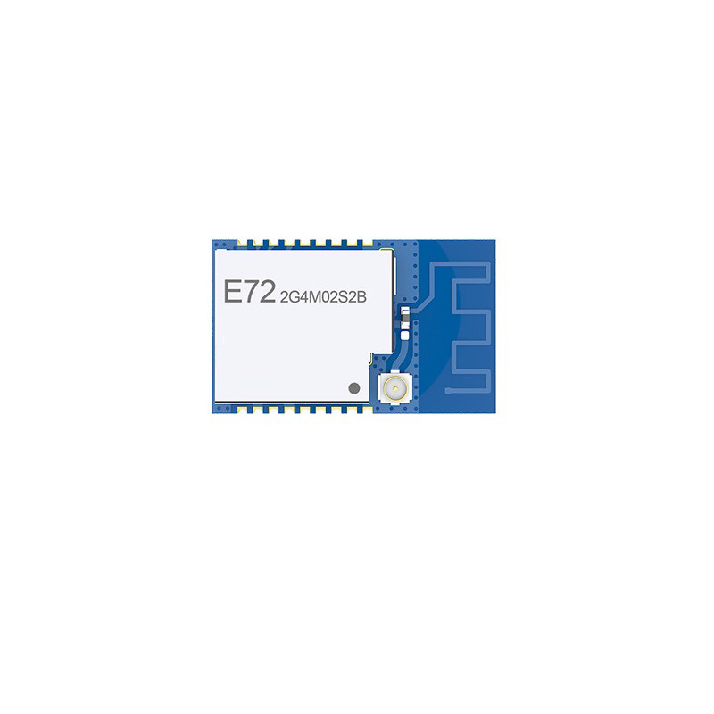
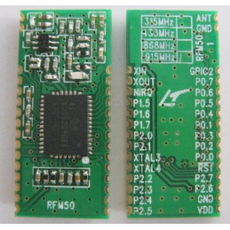
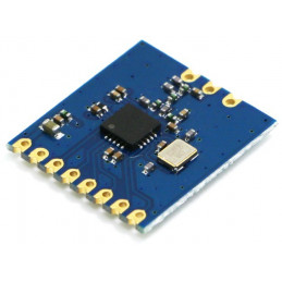
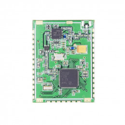
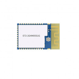
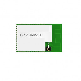
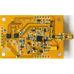
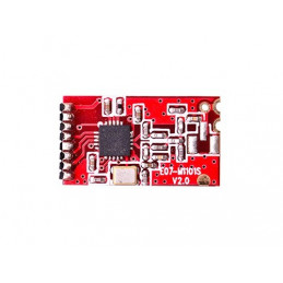
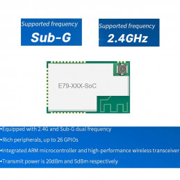
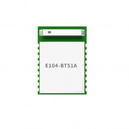
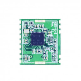
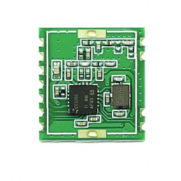
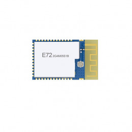
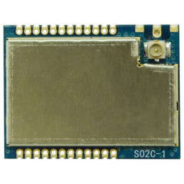
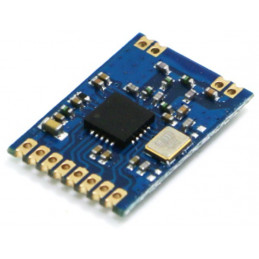
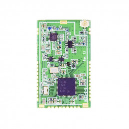
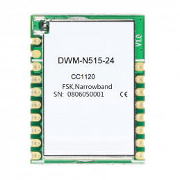
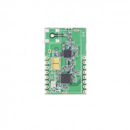
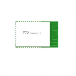
E72-2G4M02S2B is a small-size SMD RF module BLE Bluetooth wireless module independently developed based on CC2640 produced by Texas Instruments (TI)。CC2640 chip integrates 128KB intra-system programmable flash and 8KB buffer static RAM (SRAM) and different 2.4GHz wireless communication protocols. It also has a rich set of peripherals. Because of its unique ultra-low-power sensor controller, it’s ideal for connecting external sensors, and it is also suitable for autonomous collection of analog and digital data while the rest of the system is in sleep mode.Thanks to its built-in dual-core low-power processor, users can build a complete system based on their own supporting modules. We used a 24MHz industrial grade high precision low temperature drift active crystal. The module also supports secondary development. Users can write their own code to achieve the functions.
Features
The measured communication distance can reach150/300 m;
Maximum transmission power of 1.6mW, software multi-level adjustable;
Built-in BLE 4.1protocol stack;
Built-in 32.768kHz clock crystal oscillator;
Support the global license-free ISM 2.4GHz band;
Built-in high performance low power Cortex-M3 and Cortex-M0 dual core processor;
Rich resources,128KB FLASH,28KB RAM;
Support 1.8V~3.8V power supply,power supply over 3.3Vcan guarantee the best performance;
Industrial grade standard design, support -40~85°C for working over a long time;
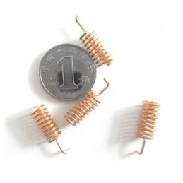
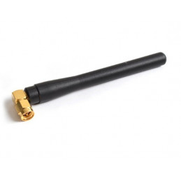
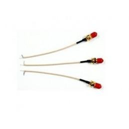
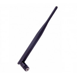
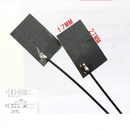
Support PCB antenna and IPEX interface, users can choose according to needs.
Application
Smart homes and industrial sensors;
Security system, positioning system;
Wireless remote control, drone;
Wireless game remote control;
Health care products;
Wireless voice, wireless headset;
Automotive industry applications.
Pin Definition(See the picture)
| Pin No. |
Item |
Direction |
Description |
| 1 |
GND |
|
Ground, connecting to power source referential ground |
| 2 |
DIO 0 |
Input/Output |
General IO port, sensor controller (see CC2640 manual for details) |
| 3 |
DIO 1 |
Input/Output |
General IO port, sensor controller (see CC2640 manual for details) |
| 4 |
RXD |
Input/Output |
Serial receive pin |
| 5 |
JTAG TMS |
Input/Output |
JTAG TMSC(see CC2640 manual for details) |
| 6 |
JTAG TCK |
Input/Output |
JTAG TCKC(see CC2640 manual for details) |
| 7 |
TXD |
Input/Output |
Serial port transmit pin |
| 8 |
DIO 4 |
Input/Output |
High drive IO,JTAG TDI(see CC2640 manual for details) |
| 9 |
GND |
|
Ground, connecting to power source referential ground |
| 10 |
nRESET |
Input |
Reset(see CC2640 manual for details) |
| 11 |
VDD |
|
D or u 1;1 QUI 2QU
Power supply:1.8V~3.8V |
| 12 |
DIO 5 |
Input/Output |
SLEEP pin. trigger and wake up
bIII1 P111, 11S5V14IIMWaMVUF |
| 13 |
GND |
|
Ground, connect to the power reference ground |
| 14 |
DIO 6 |
Input/Output |
MRDY pin. trigger serial reception
IWIILD IPiI I SI sIIdII √PUO1l |
| 15 |
DIO 7 |
Input/Output |
C
SRDY pin, wake up external MCU |
| 16 |
DIO 8 |
Input/Output |
Connection, output low level |
| 17 |
DIO 9 |
Input/Output |
General IO, sensor controller, digital analog(see CC2640 manual for
details) |
| 18 |
GND |
|
na
Ground electrode, connect to power reference ground |
| Please refer to "CC2640 Datasheet"of TI for pin definition, software drive and protocol |
Useful Link:
CC2640 Datasheet
User Manual
