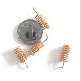


Reference: DWM14042301
Spring antenna is specialized for wireless data transmission. This antenna with good performance of V.S.W.R, small size design, easily installation, stable performance and good anti-shock and anti-aged compatible for Hoperf Modules.
Reference: DWM14032902
SMA rf antenna connector is pallets copper gold andexternal thread needle sma pallets plate rf connector.
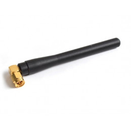
Reference: DWM14032102
Whip antenna for sub-1 GHz, 433MHz,868MHz and 915MHz with SMA male connectors.it's used with wireless module recommanded by Hoperf .
Reference: DWM14042401
SMA RG178 extension female cable for GPS, GSM antenna,RF module, SMA cable,IPEX to SMA jumper cable.
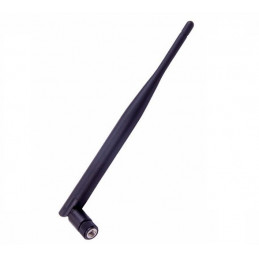
Reference: DWM18032302
USD3.0/pcs MOQ100pcs LoRa Antenna designed for Lora application which required for outdoor waterproof highgain and work at ISM free band like 433MHz /868MHz /915MHz SMA Male Whip antenna.
Reference: DWM16121503
DWM-TLB-3.0QB SUB-1GHz / 2.4GHz Whip antenna with a Collapsible SMA male connectors.Which are available for 433MHz,868MHz.915MHz and 2.4GHz..
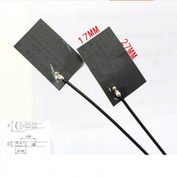
Reference: DWM17111002
LoRa Antenna-433MHz High Gain internal aerial piamater FPC Antenna with IPEX connctor.
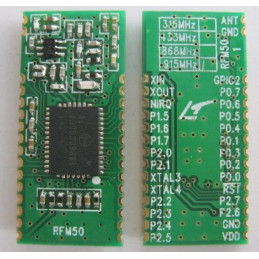
Reference: DWM15101001
Brand: Semtech
RFM50 module series’ design is based on the high performance RF50 SoC chip, It include a CIP-51 core‘ MCU and 100mW transceiver. It operate at 433/470/868/915 MHz ISM band, comply with FCC, ETSI regulation.


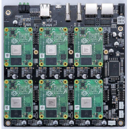
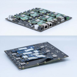
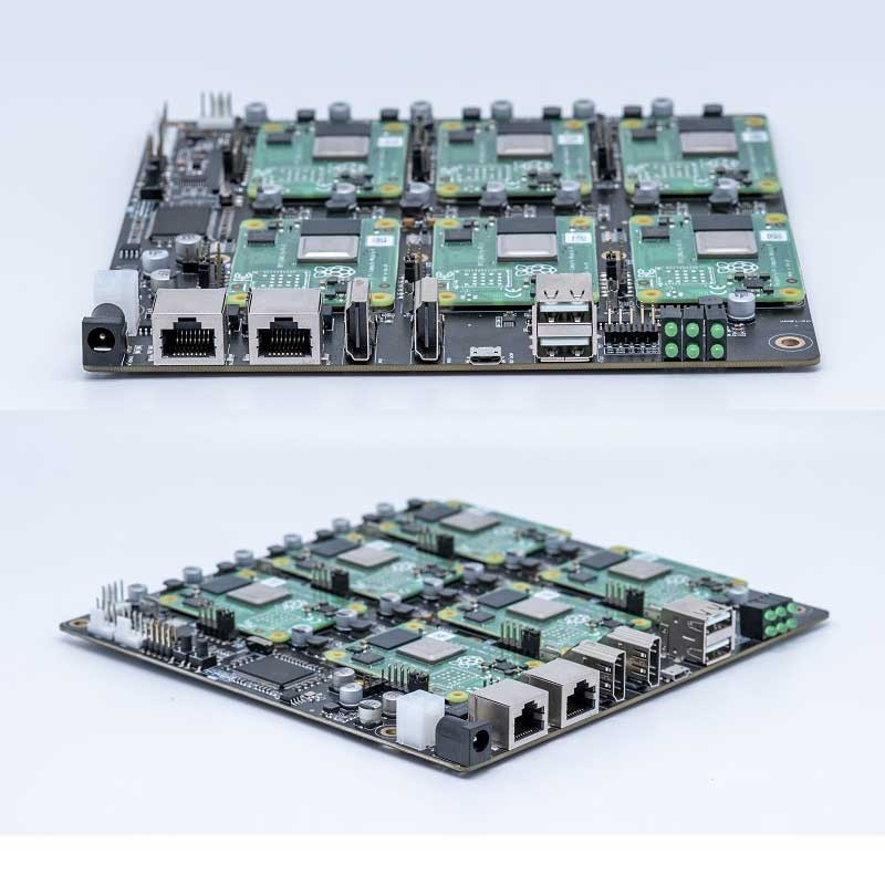
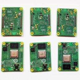
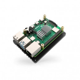
Raspberry Pi cluster board a standard size mini-ITX board to be put in a case with up to 6 RPI CM4 Compute Modules.
Raspberry Pi cluster board a standard size mini-ITX board to be put in a case with up to 6 RPI CM4 Compute Modules.
6 RPI CM4 supported
1 Gbps RJ45 x2
Onboard ON/OFF and Reset button
PC Case front panel header
12V FAN Header x3
DC 19v~24V or ATX 12V
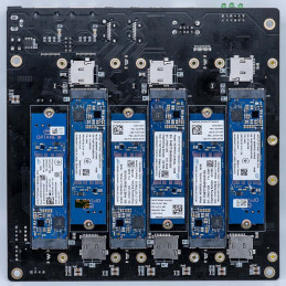
a. PCIe Gen2 x1 (M.2 M-key) (Support NVME 2280 SSD)
b. Micro SD Card socket
c. 5V FAN Header
d. Micro USB 2.0
a. USB Host A 2.0 x2
b. USB Host 2.54 4-pins x2
c. HDMI 2.0 x1
d. HDMI 1.4a x1
e. 3-PIN ARGB (5 V) (GPIO18 Support WS2812B Individually Addressable RGB (ARGB) LED )
1. 1pcs Raspberry Pi CM4 Cluster Mini-ITX board.
2. 1pcs 100W Power Adapter (UL/TUV/CCC/PSE/EK)
Note: Raspberry Pi CM4 board are not included
170mm x 170mm x 21mm (Mini-ITX)
Self-hosted: Host cloud applications locally or at the edge Learning
Learning: Kubernetes, Docker, Serverless
Development: Build cloud-native and CI/CD for ARM edge infrastructure
Network-Attached Storage or Distributed Storage System :6 x ARM NAS node or CEPH node
Home server (homelab) and cloud apps hosting.
Learn Kubernetes, Docker Swarm, Serverless, Microservices on bare metal
Cloud-native apps testing environment
Learn concepts of distributed Machine Learning apps
Prototype and learn cluster applications, parallel computing, and distributed computing concepts
Host K8S, K3S, Minecraft, Plex, Owncloud, Nextcloud, Seafile, Minio, Tensorflow
RPi CM4 ITX Cluster supports all Raspberry Pi CM4 with and without eMMC.
No, the product only have cluster motherboard and power adapter.
You can boot the OS either from eMMC, SD Card or netboot.
Yes
The nodes interconnected with the onboard 1 Gbps switch. And, each node has 1Gbps speed.
The cluster works with any amount of nodes. You can start with a couple of nodes and scale when needed.
Yes, you can flash a compute module using a Micro USB cable.
There are 2 USB-A an 2 USB 2.54 Pins on the board.They only connect to CM4 1$. The two HDMI ports are also the same.
NIC – There is an 8-port gigabit switch on the board. Each port goes to each node plus one uplink. Two RJ45 out are from the switch. You can use them connect to other network device without extern switch.
Yes.
Note: The latest Raspberry Pi OS does not contain pi user and it may not need to add dtoverlay=dwc2,dr_mode=host to config.txt file.
- Assume you are using the old version (Raspberry Pi OS 2021-11-08)
- CM4 Lite means Raspberry Pi Computer module come without a EMMC storage onboard. That means you need purchase MicroSD card(TF card).
- Steps:
 Before we unplug, now that your CM4 is fully flashed and ready to go, you’ll be surprised to learn that the USB Ports are disabled by default. Yes, really. Remember, this is a board designed to be embedded elsewhere and not for consumer-level off-the-shelf use.

In the “boot” folder, find the config.txt and add the following:

dtoverlay=dwc2,dr_mode=host

This will turn on the USB ports when you boot up, but if you accidentally keep the micro USB in, you will run into issues. Before you begin your first boot, make sure everything is unplugged. Boot and then plug in your mouse or keyboard.

If you’re like me and couldn’t get a wi-fi version, this is where you’ll plug in your dongle or ethernet cable.
Please also read the section in the Compute Module Datasheets:compute-module-datasheets-and-schematic
Ensure the Compute Module is fitted correctly installed on the IO board. It should lie flat on the IO board.
Make sure that nRPBOOT which is on J2 (disable eMMC Boot) on the IO board jumper is fitted
Use a micro USB cable to connect the micro USB slave port MCRO_USB on IO board to the host device.
Do not power up yet.
Under Windows, an installer is available to install the required drivers and boot tool automatically. Alternatively, a user can compile and run it using Cygwin and/or install the drivers manually.
For those who just want to enable the Compute Module eMMC as a mass storage device under Windows, the stand-alone installer is the recommended option. This installer has been tested on Windows 10 32-bit and 64-bit, and Windows XP 32-bit.
Please ensure you are not writing to any USB devices whilst the installer is running.
Download and run the Windows installer to install the drivers and boot tool.
Plug your host PC USB into the USB SLAVE port, making sure you have setup the board as described above.
Apply power to the board; Windows should now find the hardware and install the driver.
Once the driver installation is complete, run the RPiBoot.exe tool that was previously installed.
After a few seconds, the Compute Module eMMC will pop up under Windows as a disk (USB mass storage device).
We will be using Git to get the rpiboot source code, so ensure Git is installed. In Cygwin, use the Cygwin installer. On a Raspberry Pi or other Debian-based Linux machine, use the following command:
sudo apt update
sudo apt upgrade -y
sudo apt install git
Git may produce an error if the date is not set correctly. On a Raspberry Pi, enter the following to correct this:
sudo date MMDDhhmm
where MM is the month, DD is the date, and hh and mm are hours and minutes respectively.
Clone the usbboot tool repository:
git clone --depth=1 https://github.com/raspberrypi/usbboot
cd usbboot
libusb must be installed. If you are using Cygwin, please make sure libusb is installed as previously described. On Raspberry Pi OS or other Debian-based Linux, enter the following command:
sudo apt install libusb-1.0-0-dev
Now build and install the usbboot tool:
make
Run the usbboot tool and it will wait for a connection:
sudo ./rpiboot
Now plug the host machine into the Compute Module IO board USB slave port and power the CMIO board on. The rpiboot tool will discover the Compute Module and send boot code to allow access to the eMMC.
./rpiboot -h
After rpiboot completes, a new USB mass storage drive will appear in Windows. We recommend using Raspberry Pi Imager to write images to the drive.
Make sure J2 (nRPBOOT) is set to the disabled position and/or nothing is plugged into the USB slave port. Power cycling the IO board should now result in the Compute Module booting from eMMC.
After rpiboot completes, you will see a new device appear; this is commonly /dev/sda on a Raspberry Pi but it could be another location such as /dev/sdb, so check in /dev/ or run lsblk before running rpiboot so you can see what changes.
You now need to write a raw OS image (such as Raspberry Pi OS) to the device. Note the following command may take some time to complete, depending on the size of the image: (Change /dev/sdX to the appropriate device.)
sudo dd if=raw_os_image_of_your_choice.img of=/dev/sdX bs=4MiB
Once the image has been written, unplug and re-plug the USB; you should see two partitions appear (for Raspberry Pi OS) in /dev. In total, you should see something similar to this:
/dev/sdX    <-  Device
/dev/sdX1   <-  First partition (FAT)
/dev/sdX2   <-  Second partition(Linux filesystem)
The /dev/sdX1 and /dev/sdX2 partitions can now be mounted normally.
Make sure J2 (nRPBOOT) is set to the disabled position and/or nothing is plugged into the USB slave port. Power cycling the IO board should now result in the Compute Module booting from eMMC.
The default bootloader configuration on CM4 is designed to support bring up and development on a Compute Module 4 IO board and the software version flashed at manufacture may be older than the latest release.
For final products please consider:
Selecting and verifying a specific bootloader release. The version in the usbboot repo is always a recent stable release.
Configuring the boot device (e.g. network boot). See BOOT_ORDER section in the bootloader configuration guide.
Enabling hardware write protection on the bootloader EEPROM to ensure that the bootloader can’t be modified on remote/inaccessible products.
N.B. The Compute Module 4 ROM never runs recovery.bin from SD/EMMC and the rpi-eeprom-update service is not enabled by default. This is necessary because the EMMC is not removable and an invalid recovery.bin file would prevent the system from booting. This can be overridden and used with self-update mode where the bootloader can be updated from USB MSD or Network boot. However, self-update mode is not an atomic update and therefore not safe in the event of a power failure whilst the EEPROM was being updated.
## Modifying the bootloader configuration
cd usbboot/recovery
Replace pieeprom.original.bin if a specific bootloader release is required.
Edit the default boot.conf bootloader configuration file. Typically, at least the BOOT_ORDER must be updated:
For network boot BOOT_ORDER=0xf2
For SD/EMMC boot BOOT_ORDER=0xf1
For USB boot failing over to EMMC BOOT_ORDER=0xf15
Run ./update-pieeprom.sh to update the EEPROM image pieeprom.bin image file.
If EEPROM write protection is required then edit config.txt and add eeprom_write_protect=1. Hardware write-protection must be enabled via software and then locked by pulling the EEPROM_nWP pin low.
Run ../rpiboot -d . to update the bootloader using the updated EEPROM image pieeprom.bin
The pieeprom.bin file is now ready to be flashed to the Compute Module 4.
To flash the bootloader EEPROM follow the same hardware setup as for flashing the EMMC but also ensure EEPROM_nWP is NOT pulled low. Once complete EEPROM_nWP may be pulled low again.
# Writes recovery/pieeprom.bin to the bootloader EEPROM.
./rpiboot -d recovery
Compute Module 4 Boards and Projects
RPi CM4 ITX Cluster IO Spec v1.0
Test EVB board CM4 Cluster Mini-ITX board #425
GitHub - DeskPi-Team/super6c: Super6c stands for Super 6 CM4 Cluster.
Reference: DWM22090901
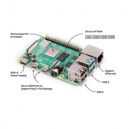
Raspberry Pi 4 Model B Broadcom BCM2711 2GB, 4GB or 8GB LPDDR4-3200 SDRAM available dual-band 2.4/5.0 GHz wireless LAN, Bluetooth 5.0, Gigabit Ethernet, USB 3.0, and PoE capability.
Reference: DWM22090802
Raspberry Pi 3 Model B+ boasting a 64-bit quad core processor running at 1.4GHz, dual-band 2.4GHz and 5GHz wireless LAN, Bluetooth 4.2/BLE, faster Ethernet, and PoE capability via a separate PoE HAT.
Reference: DWM22091001
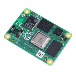
CM4 Raspberry pi Computer module 4 with wireless check out the full range of Compute Modules 4.
Reference: DWM22091205
CM4 Raspberry pi Computer module 4 without wireless check out the full range of Compute Modules 4.
Reference: DWM22090802
Raspberry Pi 3 Model B+ boasting a 64-bit quad core processor running at 1.4GHz, dual-band 2.4GHz and 5GHz wireless LAN, Bluetooth 4.2/BLE, faster Ethernet, and PoE capability via a separate PoE HAT.
Reference: DWM22091001
CM4 Raspberry pi Computer module 4 with wireless check out the full range of Compute Modules 4.
Reference: DWM22123001
The Raspberry Pi 4 Model B is the best single-board computer to develop your IoT project, and start your first gateway for NB-IoT/Cat-M and LoRaWAN with the RAK Pi HAT.
Reference: DWM22081701
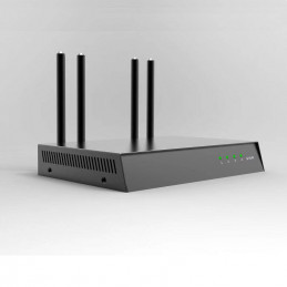
HNT SNR full frequency transmitter is to simultaneously transmit the weak dynamic interference energy of 8 witness bands of helium to suppress the SNR value of HNT miner witness, further improve the authenticity of SNR simulation, reduce the probability of blacklisting.
Reference: DWM22072501
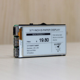
LILYGO 3.71 inch ink screen with touch can be used as a Raspberry Pi expands the module, and the corresponding pin-out interface is designed to adapt to the Raspberry Pi.
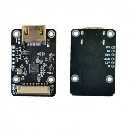
Reference: DWM22101001
HDMI to CSI-2 Adapter Board built by TC358743XBG is an HDMI to CSI-2 camera port adapter designed for Raspberry Pi with up to 1080p@30fps support.all versions of Raspberry Pi series boards are supported.
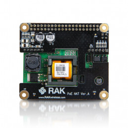
Reference: DWM22123003
RAK9003 PoE Pi HAT can power the RPi 3B+ and RPi 4 directly through your gateway's Ethernet port. suitable for deployments utilizing cabled network connectivity.
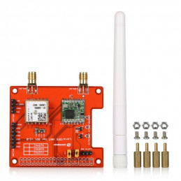
Reference: DWM16092702
The Lora/GPS_HAT is an expension module for LoRaWan for using with the Raspberry Pi.This product is intended for those interested in developing LoRaWAN solutions which is based on the SX1276/SX1278 transceiver.
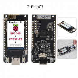
Reference: DWM22072502
The T-PicoC3 ESP32-C3 RP2040 Wireless WIFI Module is a Dual MCUs board Equipped with Raspberry Pi RP2040 and ESP32-C3 chip Support learning library TensorFlow, via TensorFlow Lite With 1.14in ST7789V IPS high definition LCD.
Reference: DWM24012302
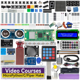
The SunFounder Raspberry Pi Pico W Ultimate Starter Kit offers a rich IoT learning experience for beginners aged 8+. With 450+ components,117projects, and expert-led video lessons, this kit makes learning microcontroller programming and IoT engaging and accessible.
Reference: DWM22090901
Raspberry Pi 4 Model B Broadcom BCM2711 2GB, 4GB or 8GB LPDDR4-3200 SDRAM available dual-band 2.4/5.0 GHz wireless LAN, Bluetooth 5.0, Gigabit Ethernet, USB 3.0, and PoE capability.
Reference: DWM23041902
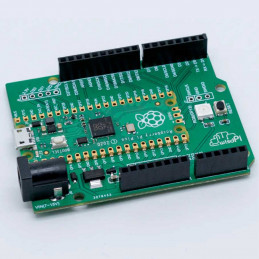
ArduPico is An Arduino-style Carrier board which compatible Raspberry Pi Pico/Pico H/Pico W/Pico WH.
Reference: DWM22091101
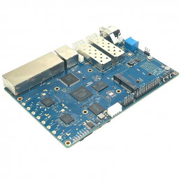
BPI-R3 Router board with MediaTek MT7986(Filogic 830) quad core ARM A53 + MT7531A chip design ,2G DDR RAM ,8G eMMC flash onboard, it is a very high-performance open-source router development board, support Wi-Fi 6/6E 2.4G Wi-Fi use MT7975N and 5G Wi-Fi use MT7975P, support 2 SFP 2.5GbE port, and 5 GbE network port.
Reference: DWM22101302
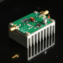
433MHz 8W amplifier Board is high Efficiency for data transmission, flight control, extended range RF power amplification.
Reference: DWM22091205
CM4 Raspberry pi Computer module 4 without wireless check out the full range of Compute Modules 4.
Reference: DWM22090803
The Raspberry Pi 3 Model B is based on the 64-bit quad-core Broadcom BCM2837 ARMv8 core with a processor clock of 1.2 GHz and is therefore up to ten times more powerful than a first-generation Raspberry Pi with wireless LAN and Bluetooth connectivity.
Raspberry Pi cluster board a standard size mini-ITX board to be put in a case with up to 6 RPI CM4 Compute Modules.