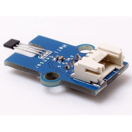
Features
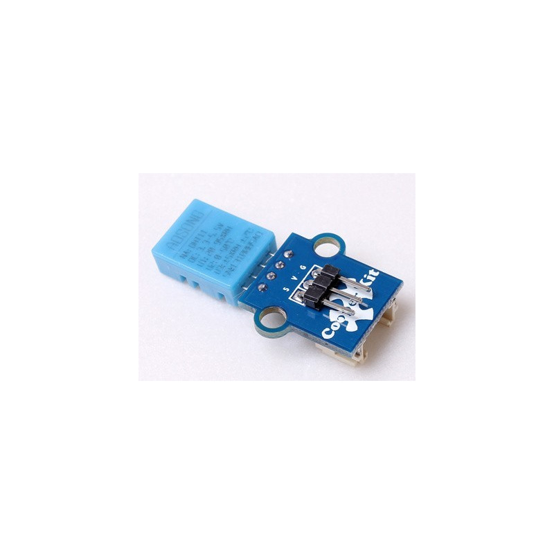
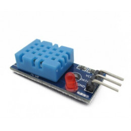
- 1. Plug and play, easy to use. Compatible with the mainstream 2.54 interfaces and 4-Pin Grove interfaces in the market..
- 2. With use of M4 standard fixed holes, compatible with M4-standard kits such as Lego and Makeblock.
- 3. Rotatable detecting direction for better adaption.
Specifications
PCB size |
22.0mm X 20.5mm X 1.6mm
|
|
Working voltage
|
3.3 or 5V DC
|
|
Operating voltage
|
3.3 or 5V DC
|
|
Measurement range
|
20-95%RH; 0-50℃
|
|
Resolution
|
8bit (temperature), 8bit (humidity)
|
|
Compatible interfaces
|
2.54 3-pin interface and 4-pin Grove interface(1)
|
Note 1: S for digital output port, V and G for voltage at the common collector and ground respectively.
Electrical characteristics
|
|
Min.
|
Typical
|
Max.
|
Unit
|
|
Working voltage
|
3
|
5
|
5.5
|
VDC
|
|
Working current (VCC=5V, T=25℃)
|
0.5
|
-
|
2.5
|
mA
|
|
Sampling interval
|
1
|
-
|
-
|
s
|
|
Humidity
|
|
Accuracy
|
25℃
|
-
|
±4
|
-
|
%RH
|
|
0-50℃
|
-
|
-
|
±5
|
%RH
|
|
Measurement range
|
25℃
|
20
|
-
|
95
|
%RH
|
|
Response time
|
1/e (63%) 25℃, 1m/s air
|
6
|
10
|
15
|
s
|
|
Temperature
|
|
Accuracy
|
±1
|
-
|
±2
|
℃
|
|
Measurement range
|
0
|
-
|
50
|
℃
|
|
Response time
|
/e (63%)
|
6
|
|
30
|
s
|
Communication Process: Serial Interface (Single-Wire Two-Way)
Single-bus data format is used for communication and synchronization between MCU and DHT11 sensor. One communication process is about 4ms. Data consists of decimal and integral parts, and the specific format will be described below. Current decimal part is for future expansion which is read as zero now. The operation process is as below: a complete data transmission is 40bit, and the sensor sends higher data bit first.
Data format: 8bit integral RH data + 8bit decimal RH data + 8bit integral T data + 8bit decimal T data + 8bit check sum. If the data transmission is right, the check-sum should be the last 8bit of "8bit integral RH data + 8bit decimal RH data + 8bit integral T data + 8bit decimal T data".
When MCU sends a start signal, DHT11 changes from the low-power-consumption mode to the running-mode. Once the start signal is completed, DHT11 sends a response signal of 40-bit data and trigger a signal acquisition. Users can choose to collect (read) some data. Without the start signal from MCU, DHT11 will not collect temperature & humidity information spontaneously. Once data is collected, DHT11 will change to the low-power-consumption mode until it receives a start signal from MCU again.
1. Communication process is shown in the following diagram

Free status of data single bus is at high voltage level. MCU needs to pull down bus for more than 18ms to wait for response from DHT11 to make sure that DHT11 can detect the start signal. Once DHT11 receives the start signal from MCU, it will wait to send 80us low level response signal till the start signal is over. After the start signal from MCU is over, delay and wait for 20-40us, then read the response signal of DHT11. After MCU sends the start signal, it can switch to input mode or output high level, while the bus will be pulled up by the pull-up resistor.
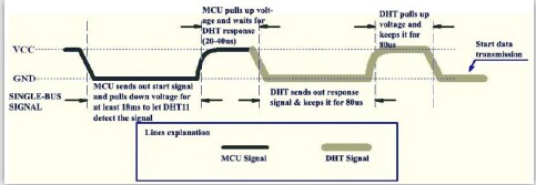
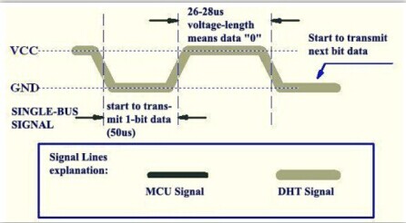
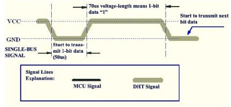
When the bus is at low level, it indicates that DHT11 sent a response signal, after which, pull up the bus for 80us. When sending data, every bit of data begins with the 50us low-voltage-level and the length of the following high-voltage-level signal determines whether data bit is "0" or "1". Format is shown in the following diagram. If the response signal read is high level, DHT11 will not respond, please check the cable connections.After last bit of data is transmitted, DHT11 will pull down bus for 50us, then bus will be pulled up by pull-up resistor into free status.
2. Signal indication of data 0 is shown in the following diagram.
3. Signal indication of data 1 is shown in the following diagram.
Demo for CoX Library
#include "CooperKit_DHT11.h"
/*
 * Connect the S port of CooperKit DHT11 switch to D0 Pin of Connect shield,
 * and we will use the following program to read the Temperature and ucHumidity.
 */
void DHT11_example(void)
{

        unsignedchar ucTemperature =0, ucHumidity =0;

        while(1)
        {
            DHT11ReadData(&ucTemperature,&ucHumidity);
        }

}
How to Port
This demo is based on CoX M051 library, if you want to port to other CoX library, Just do the simple step below.
The DHT11 driver is commucate with GPIO pin, so in the CooperKit_DHT11.h file, the port configuration group provides the gpio pin connection Macro to user for port. For example your Button signal pin is connect to GPIOA PIN2, you should modify the Macro as:
//*****************************************************************************
//
//! \addtogroup DHT11_Config_Pins DHT11 Driver Pin Configurtion
//!
//! \brief GPIO Pins Configurtions that communication with the Sensor should be
//! set before using this driver.
//!
//! @{
//
//*****************************************************************************
#define DHT11_PIN_DATA          PA2

//*****************************************************************************
//
//! @}
//
//*****************************************************************************
