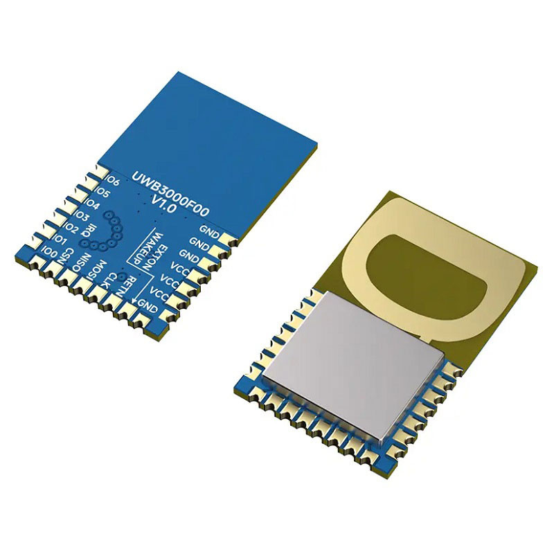
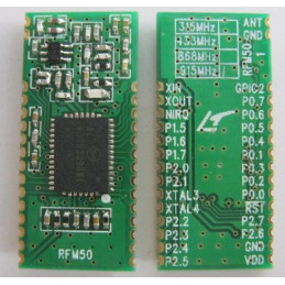
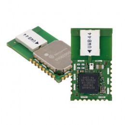
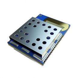
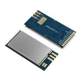
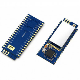
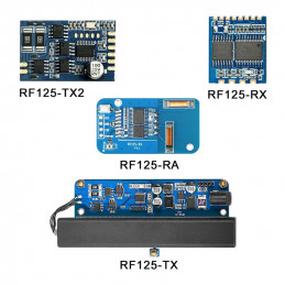
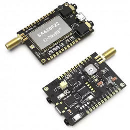
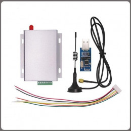
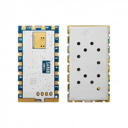
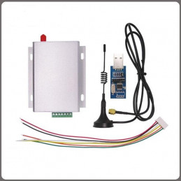
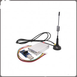
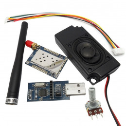
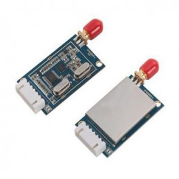
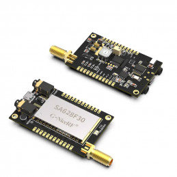
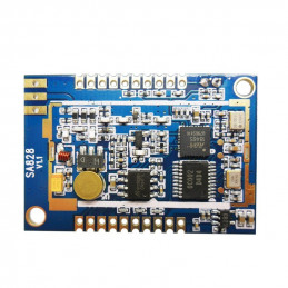
The UWB3000F00 adopted Qorvo's DW3000, designed with PCB Antenna. UWB3000 is in line with IEEE802.15.4-2015 and IEEE802.15.4z (BPRF mode). It can be used for two-way ranging, TDOA, and PDOA systems, with a positioning accuracy of 10 cm.
Features
Core chipset: DW3000
Frequency: 6489.6 MHz & 7987.2 MHz
positioning accuracy: Asset location to an accuracy of 10 cm
Data rates: 850 kbps and 6.8 Mbps
I15.4-2015 UWB
15.4z(BPRF mode)
Supports channels 5 & 9(6489.6 MHz & 7987.2 MHz)
Data rates of 850 kbps and 6.8 Mbps
Integrated HW AES 256
Worldwide UWB Radio
Regulatory compliance
Packet length up to 1023 bytes
Supports 2-way ranging, TDoAand PDoA location schemes
Programmable output power
Provides precision location and data transfer simultaneously
Asset location to an accuracy of 10 cm
Low power consumption for coin cell applications
Applications
Precision real-time location systems (RTLS) using two-way ranging, TDoA or PDoA schemes in a variety of markets: Healthcare\ Consumer\ Industrial\ Automotive
Location-aware wireless sensor networks
Presence detection for secure entry and secure payment
Parameters:
|
Parameter
|
Condition
|
Min.
|
Typ.
|
Max.
|
Unit
|
|
Supply Voltage
|
|
2.4
|
3.3
|
3.6
|
V
|
|
Operating Temperature Range
|
|
- 40
|
25
|
85
|
℃
|
|
Frequency Range
|
CH5
|
|
6489.6
|
|
MHz
|
|
CH9
|
|
7987.2
|
|
MHz
|
|
RF Data Rate
|
|
850k
|
|
6.8M
|
bps
|
|
Current Consumption
|
|
Sleep Mode
|
|
|
< 1
|
|
uA
|
|
Rx CH5
|
|
|
72
|
|
mA
|
|
Rx CH9
|
|
|
88
|
|
mA
|
|
Tx
|
|
|
69
|
|
mA
|
|
TX for range measurement
|
|
|
21
|
|
mA
|
|
Transmit parameters
|
|
Tx Power
|
@VCC=3.3V
|
-30
|
|
0
|
dBm
|
|
Tx Bandwidth(BW)
|
|
|
499.2
|
|
MHz
|
|
Receive parameters
|
|
Rx Sensitivity
|
@850Kbps
|
|
-100
|
|
dBm
|
|
@6.8Mbps
|
|
-94
|
|
dBm
|
Pin Definitions:
|
Pin No.
|
Pin definition
|
I/O
|
Description
|
|
1,2,3,7
|
GND
|
|
Ground
|
|
4,5,6
|
VCC
|
|
VCC (2.4-3.6v)
|
|
8
|
EXTON
|
DO
|
External device enable. Asserted during the wake-up process and held active until the device enters sleep mode. Can be used to control external DC-DC converters or other circuits that are not required when the device is in sleep mode so as to minimize power consumption.
|
|
9
|
WAKEUP
|
DI
|
When asserted into its active high state, the WAKEUP pin brings the DW3000 out of SLEEP or DEEPSLEEP states into operational mode.
This should be connected to the ground if not used.
|
|
10
|
NRSTn
|
DIO
|
Reset pin. Active Low Output.
May be pulled low by an external open drain driver to reset the DW3000.
Must not be pulled high by an external source.
|
|
11
|
CLK
|
DI
|
SPI peripheral clock input.
|
|
12
|
MOST
|
DI
|
SPI peripheral data input.
|
|
13
|
MISO
|
DO
|
SPI peripheral data output.
|
|
14
|
CSN
|
DI
|
SPI chip select. This is an active low enable input. The high-to-low transition on SPICSn signals the start of a new SPI transaction. SPICSn
can also act as a wake-up signal to bring DW3000 out of either SLEEP or DEEPSLEEP states.
|
|
15
|
IRAQ
|
DI
|
Interrupt request output from the DW3000 to the host processor. By
default, IRQ is an active-high output but may be configured to be active
low if required. Correct operation in SLEEP and DEEPSLEEP modes should be configured for active high operation. This pin will float in SLEEP and DEEPSLEEP states and may cause spurious interrupts on the host unless pulled low externally (100kΩ recommended). When the IRQ functionality is not being used the pin may be reconfigured as a general-purpose I/O line2, GPIO8.
|
|
16
|
GPIO0
|
DIO
|
GPIO0 from DW3000.
|
|
17
|
GPIO1
|
DIO
|
GPIO1 from DW3000.
|
|
18
|
GPIO2
|
DIO
|
GPIO2 from DW3000.
|
|
19
|
GPIO3
|
DIO
|
GPIO3 from DW3000.
|
|
20
|
GPIO4
|
DIO
|
GPIO4 from DW3000.
|
|
21
|
GPIO5
|
DIO
|
GPIO5 from DW3000.
|
|
22
|
GPIO6
|
DIO
|
GPIO6 from DW3000.
|
Package Include:
Start KIT
2 x UWB3000F00 Demo Board
Module
1 x UWB3000F00 Module.
Useful Link:
Datasheet
UWB DW3000 Arduino
UWB3000FX Demo Board User Guide
