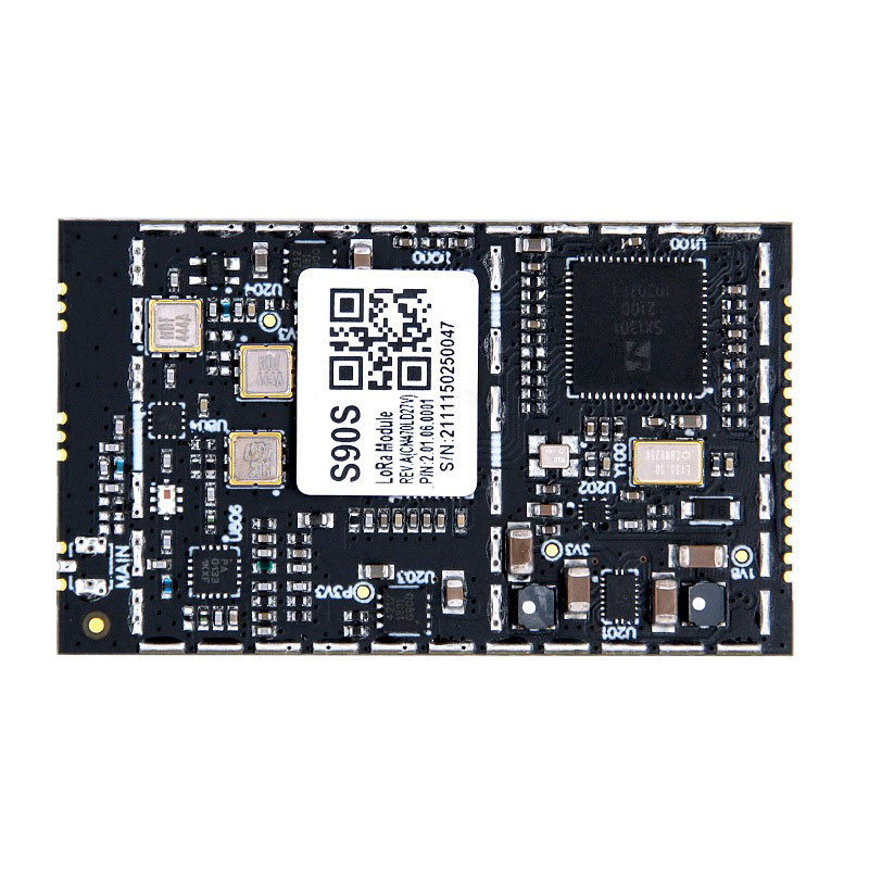
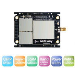
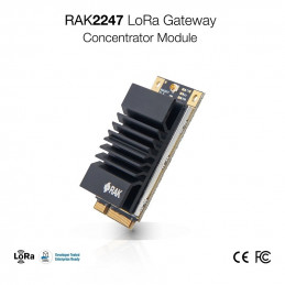
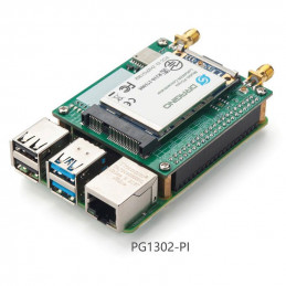
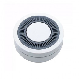
TheDWM-S90S LoRa base station module (SPI) is a series of gateway communication modules that comply with the LoRaWAN international communication specification. The module is packaged in a stamp hole and provides an SPI communication interface, which can be embedded on the user's main board, so that the user's main board has the function of LoRaWAN gateway.
DWM-S90S supports 8 simultaneous uplink channels, EU433/CN470/EU868/US915 multi-band optional, allowing access to various LoRa applications. The gateway module can be connected to the standard LoRaWAN core network server, allowing users to easily and quickly access the IoT system.
DWM-S90S series is based on SX1301+SX1255 chip combination, supports LoRaWAN standard protocol Class A/B/C equipment, has 8 uplink channels,1 downlink channel, the maximum transmit power is +27dBm, and the maximum receiving sensitivity is -140dbm.
Features
LoRaWAN standard protocol V1.0.2
EU433/CN470/EU868/US915 multi-band optional
Support Class A/B/C equipment
8 upstream channels,1downstream channel
Communication rate 292bps~5.4kbps
Transmit Power: Default +17dBm / +27dBm Max
The maximum receiving sensitivity is -140dbm (@SF=12, BW=125KHz)
SPI communication interface
Package form: stamp hole patch type
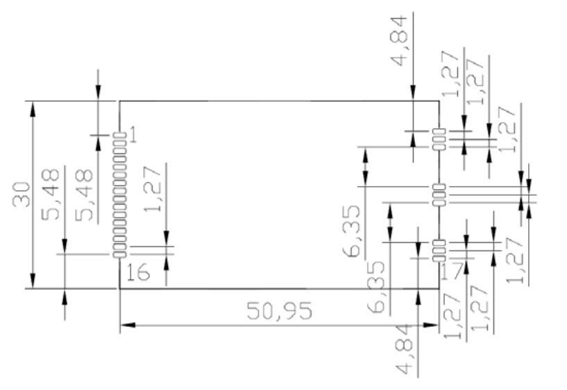
Mechanical dimension: L×W×H=30×51×2.65mm
Working voltage:3.6~5VDC
Working temperature:-40℃ to +85℃
Storage temperature:-40℃ to +85℃
Passed FCC, CE, RoHS certification
Application
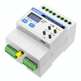
LoRaWAN three-meter collection
Collection of energy consumption in public buildings
Wireless smoke sensor
Building HVAC control
Municipal Lighting Control
Pin description
| Num |
Pin name
|
Direction |
Function |
Notes
|
| 1 |
GND |
- |
modular ground |
module ground wire, and as close to the regulator GND pin as possible |
| 2 |
GND |
- |
modular ground |
module ground wire, and as close to the regulator GND pin as possible |
| 3 |
VDD |
- |
Module power input |
The input voltage range is 3.6~5V |
| 4 |
VDD |
- |
Module power input |
The input voltage range is 3.6~5V |
| 5 |
GPIO4 |
I/O
|
54/GPIO[4] |
SX1301 pin 54/GPIO[4] |
| 6 |
GPIO3 |
I/O
|
55/GPIO[3] |
SX1301 pin 55/GPIO[3] |
| 7 |
GPIO2 |
I/O
|
56/GPIO[2] |
SX1301 pin 56/GPIO[2] |
| 8 |
GPIO1 |
I/O
|
57/GPIO[1] |
SX1301 pin 57/GPIO[1] |
| 9 |
GPIO0 |
I/O
|
58/GPIO[0] |
SX1301 pin 58/GPIO[0] |
| 10 |
RESET |
I |
1/RESET |
SX1301 pin 1/RESET |
| 11 |
GND |
- |
modular ground |
module ground wire, and as close to the regulator GND pin as possible |
| 12 |
SCK |
O |
2/HOST_SCK |
SX1301 pin 2/HOST_SCK |
| 13 |
MISO |
I |
3/HOST_MISO |
SX1301 pin 3/HOST_MISO |
| 14 |
MOSI |
O |
4/HOST_MOSI |
SX1301 pin 4/HOST_MOSI |
| 15 |
CSN |
O |
5/HOST_CSN |
SX1301 pin 5/HOST_CSN |
| 16 |
PPS |
I |
9/GPS_IN |
SX1301 pin 9/GPS_IN |
| 17 |
GND |
- |
modular ground |
module ground wire, and as close to the regulator GND pin as possible |
| 18 |
N.C. |
- |
empty |
Feet floating, not connected |
| 19 |
GND |
- |
modular ground |
module ground wire, and as close to the regulator GND pin as possible |
| 20 |
GND |
- |
modular ground |
module ground wire, and as close to the regulator GND pin as possible |
| 21 |
N.C. |
- |
empty |
Feet floating, not connected |
| 22 |
GND |
- |
modular ground |
module ground wire, and as close to the regulator GND pin as possible |
| 23 |
GND |
- |
modular ground |
module ground wire, and as close to the regulator GND pin as possible |
| 24 |
RF-OUT |
O |
RF signal |
Module RF signal 1, 50ohm impedance |
| 25 |
GND |
- |
modular ground |
module ground wire, and as close to the regulator GND pin as possible |
Mechanical dimensions
Useful Link:
Sx1301 Datasheet
Application Notes
