- On sale!
Reference: DWM14042301
Spring antenna is specialized for wireless data transmission. This antenna with good performance of V.S.W.R, small size design, easily installation, stable performance and good anti-shock and anti-aged compatible for Hoperf Modules.
Reference: DWM14032902
SMA rf antenna connector is pallets copper gold andexternal thread needle sma pallets plate rf connector.
Reference: DWM14032102
Whip antenna for sub-1 GHz, 433MHz,868MHz and 915MHz with SMA male connectors.it's used with wireless module recommanded by Hoperf .
Reference: DWM14042401
SMA RG178 extension female cable for GPS, GSM antenna,RF module, SMA cable,IPEX to SMA jumper cable.
Reference: DWM18032302
USD3.0/pcs MOQ100pcs LoRa Antenna designed for Lora application which required for outdoor waterproof highgain and work at ISM free band like 433MHz /868MHz /915MHz SMA Male Whip antenna.
Reference: DWM16121503
DWM-TLB-3.0QB SUB-1GHz / 2.4GHz Whip antenna with a Collapsible SMA male connectors.Which are available for 433MHz,868MHz.915MHz and 2.4GHz..
Reference: DWM17111002
LoRa Antenna-433MHz High Gain internal aerial piamater FPC Antenna with IPEX connctor.
Reference: DWM15101001
Brand: Semtech
RFM50 module series’ design is based on the high performance RF50 SoC chip, It include a CIP-51 core‘ MCU and 100mW transceiver. It operate at 433/470/868/915 MHz ISM band, comply with FCC, ETSI regulation.


Setting up a LoRa peer-2-peer communication by using CY8CKIT-062-BLE with Arduino Shield (Dragino LoRa, RFM95W).
This project example describes a basic hardware setup that allows a LoRa based wireless peer-2-peer (device-2-device) communication on a proprietary protocol. It is used to validate the hardware setup, PSoC 6 MCU and external radio module.
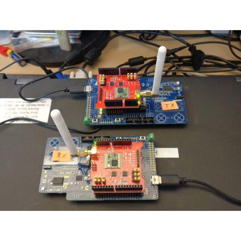
Each device consists of a PSoC 6 MCU pioneer kit (CY8CKIT-062-BLE) and an Arduino Shield (Dragino LoRa) with mounted LoRa radio module (RFM95W).
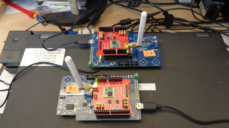
Figure 1 shows both PSoC 6 MCU pioneer kits with mounted Dragino LoRa shield. One kit has running a transmitter software, the other one has been configured as receiver.
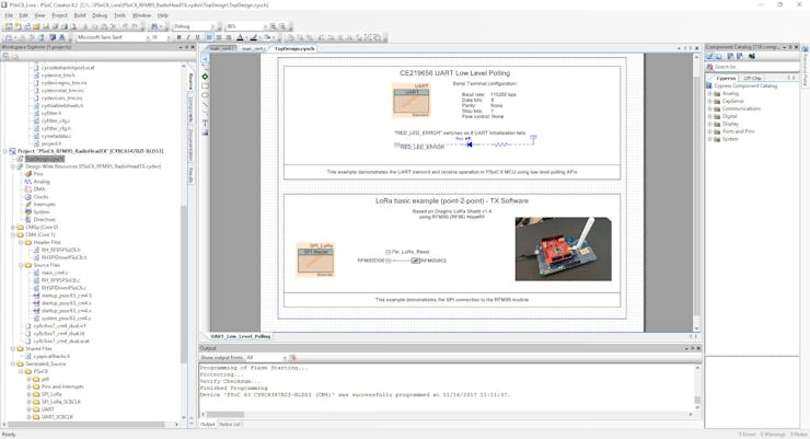
The radio module is interfaced by SPI. Further one external interrupt is used to indicate radio events. The project has been realized by PSoC Creator, see Figure 2, having the components configured accordingly. Additionally, an UART and LED has been configured for HMI and debug channel.
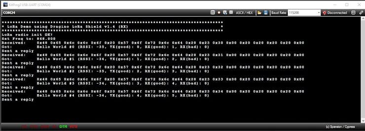
After programming the dedicated TX and RX project to the PSoC 6 MCU Pioneer kit the system is ready. The transmitter will send a packet that is been shown and additionally answered by the receiver with a reply packet.
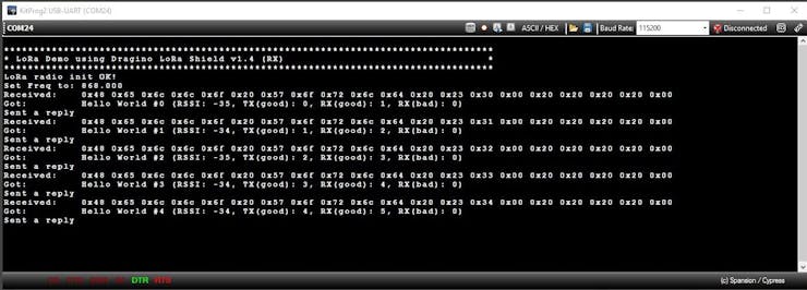
The debug output of the transmitter (here: COM13) and receiver (here: COM24) is shown in Figure 3 and Figure 4. Each sent package (“Hello World #”), having a sequential number added, is received and output via the receiver UART. The HEX values as well as the ASCII characters are printed out. The receiver confirms the receptions by sending himself a reply (“And hello back to you”) that finally is showing up in the transmitter’s (now working for short while as receiver) debug window.
After the initial test worked fine to bridge approx. 10cm (see Figure 1) using LoRa communication the transmitter has then been put into the basement while the receiver was running in 4th floor (opposite site of department) – it still was working without packets getting lost. Awesome!
The LoRa communication has been established successfully by the given setup.
This project should be taken as a very basic proof-of-concept, allowing to validate mainly the hardware required for LoRa communication that is needed for future LoRaWAN projects.
It does not claim to cover all LoRa aspects, especially related to distance range or low power considerations. Those investigations must be done within one of the next steps.
The appendix below gives details on the hard- and software used for the described system.
Within this section detailed information is given to reproduce the system described above.
The following hardware is needed:
This shield is well documented and has its own website (Wiki-page) where all project details are listed: https://wiki.dragino.com/index.php
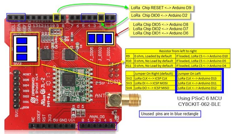
To use the shield on the PSoC 6 MCU Pioneer kit the following jumper settings are required:
The shield uses a radio module RFM95W manufactured by HopeRF, based on Semtech SX1276.
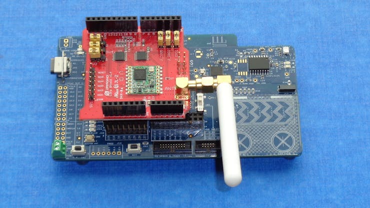
Do not forget to mount the antenna and add the Dragino LoRa shield carefully to the PSoC 6 MCU pioneer kit, as shown in Figure 5.
The complete software project is attached to this project. Nevertheless, newer versions of the used library may exist. The following section describes the used compilation:
The following software library modules are required
Most modifications have been required for the RHSPIDriver in order to adapt to the PSoC 6 MCU UART peripheral using the PDL API.
Further modifications are caused by the Arduino naming conventions that needed to be changed for standard-‘C’.
The main project has been ported from the Arduino based project found here: https://learn.adafruit.com/adafruit-rfm69hcw-and-rfm96-rfm95-rfm98-lora-packet-padio-breakouts/rfm9x-test#basic-rx-and-tx-example
The completely ported software project is attached to this memo.
Next step to enter a network... Coming soon. Stay tuned!
Usful Link:
Contact: Holger
Software: Cypress PSoC Creator
Reference: DWM16122201
The 433MHz /868MHz /915MHz Arduino LoRa Shield is a long range transceiver on a Arduino shield form factor and based on Open source library.Compatible with Arduino Leonardo, Uno, Mega, DUE.
Reference: DWM18110902
Getting started with LoRaWAN for Cypress PSoC 6 MCU based on LMiC to access to LoRaWAN TTN (The Things Network) using Dragino LoRa gateway, RFM95W.
Reference: DWM18110902
Getting started with LoRaWAN for Cypress PSoC 6 MCU based on LMiC to access to LoRaWAN TTN (The Things Network) using Dragino LoRa gateway, RFM95W.
Reference: DWM18110801
Build your own LoRaWAN "The Things Network" packet-forwarding gateway on Windows 10 IoT Core in native .NET code.

Setting up a LoRa peer-2-peer communication by using CY8CKIT-062-BLE with Arduino Shield (Dragino LoRa, RFM95W).