How to fill the Shopping-Shipping agent form ?
Shopping-Shipping Agent service from China
1.Select the Shopping-Shipping agent.
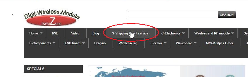
click-shopping-shipping agent
2.Download the Shopping-Shipping agent form.
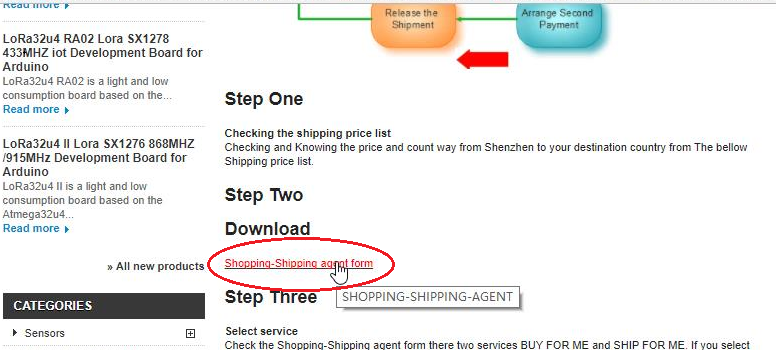
download-shopping-shipping-agent
3. Open the downloaded Shopping-Shipping agent form.
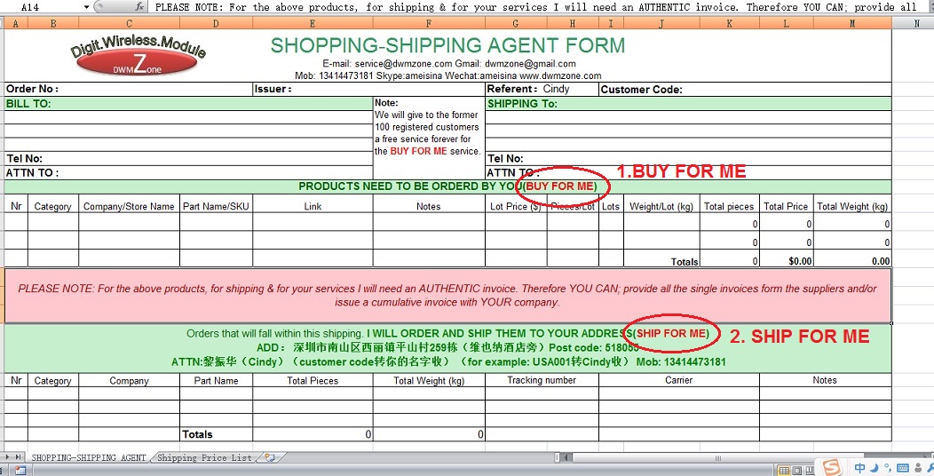
Shopping-Shipping-agent-form
You will see There Two Services BUY FOR ME and SHIP FOR ME.
3. There are required information for delivery. Contact name, Delivery address, Phone number,Some country or region also need the Tax ID.
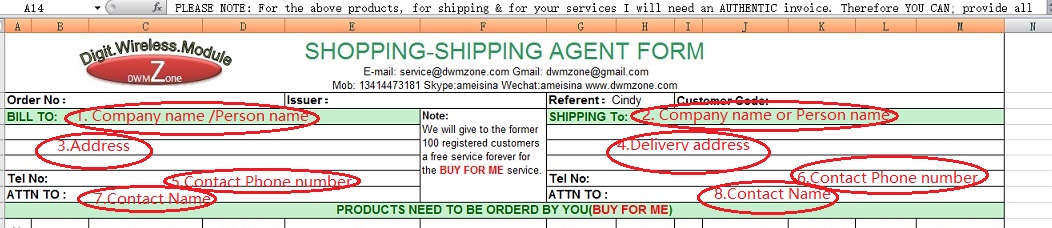
Shopping-Shipping-agent-form-contact-information
4. BUY FOR ME required information.
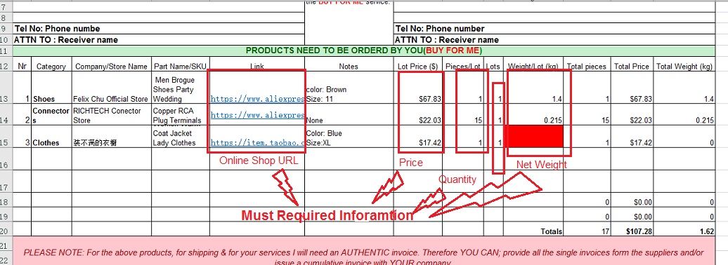
BUY-FOR-ME-required-information
5. SHIP FOR ME Required Information. Must requre Your supplier Name, Part name and the total quantity.
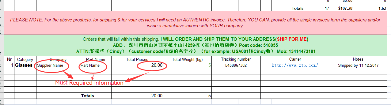
SHIP-FOR-ME-must-required-information
6. After you fill the required information then you send the form back to us.we will check and confirm with you for more details.
Here is our contact information:
E-mail: service@odlstore.com Gmail: dwmzone@gmail.com
Wechat:ameisina Skype:ameisina QQ:544209846
See the procces Pls visit:
Shopping-Shipping Agent service from China