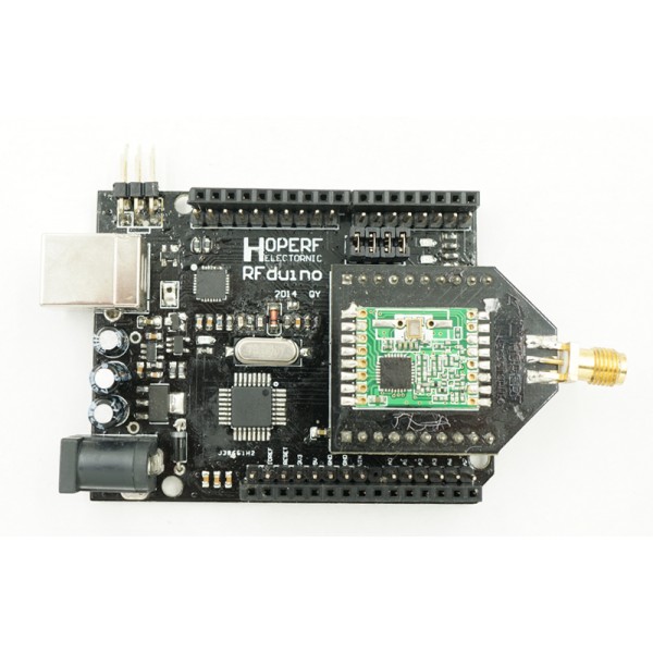
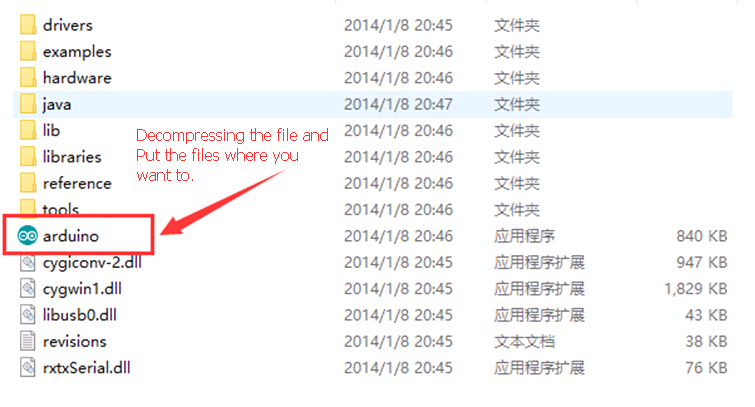
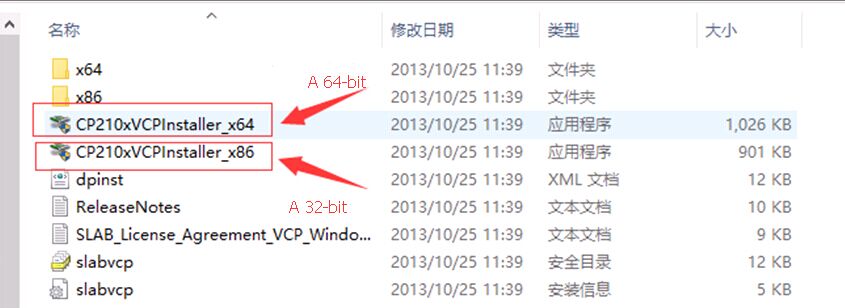
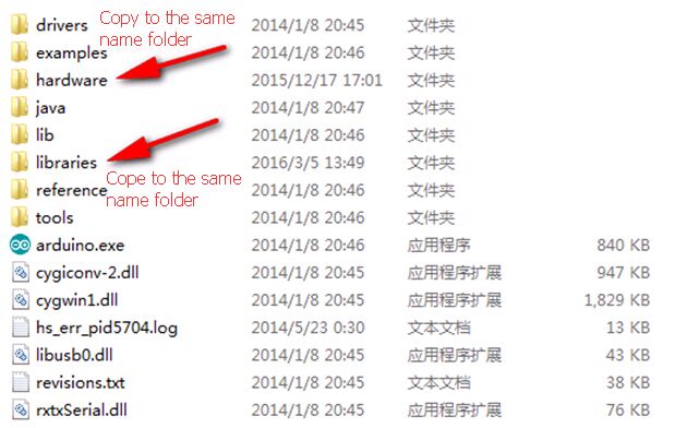
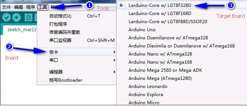
RFduino Board original design for all of the Wireless modules can share with same Library and can run a Wireless communication code with the RFduino Board.This User guide will show you how to use the RFduino Board to delevelop the RFM92W,RFM95W,RFM96W,RFM98W LoRa module etcs.
RFduino Board which also name HopeDuino But we used to call it as RFduino board.If there are any questions please contact us sales@odlstore.com. We will give more details about the name.
If you are the firt time use the RFduino Board please visit the RFduino Board User Manule.
- Prepare Hardware and software:
- RFduino Board(2pcs)
- Arduino 1.0.5 version IDE
- USB cable (A mouth turn B)
- LoRa module EVB/DK Kits
2. Operation
1.) Set two RFM9X LoRa module to The RFduino Board .
2.) Connect the RFduino Board to the PC by USB cable.
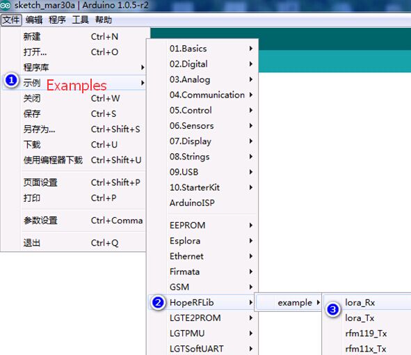
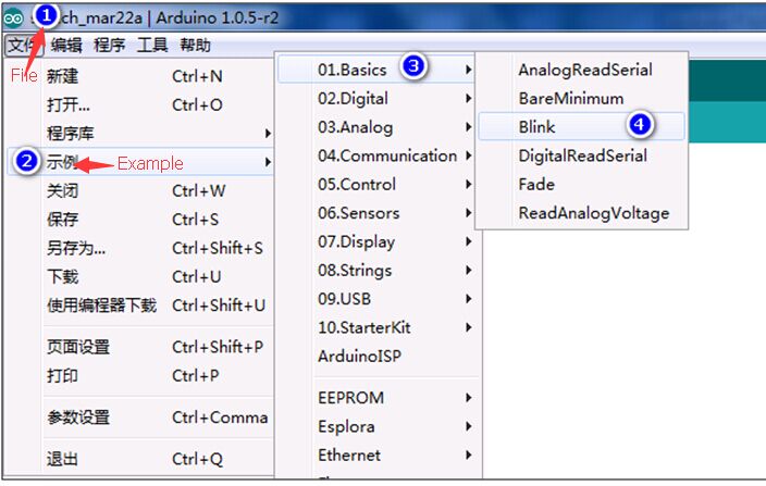
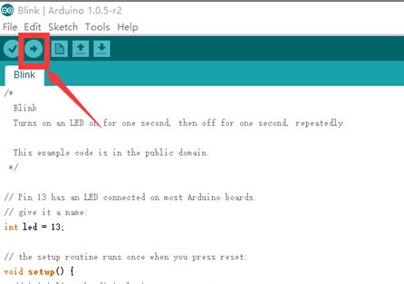
3.) Opens the Arduino IDE interface, click on the [file] – > [Examples] -> [HopeRFLib] ->[lora_Tx], below operation;
4.) Opens the Arduino IDE interface, click on the [file] – > [example] -> [HopeRFLib] -> [lora_Rx], the following figure.
5.) Compile and download the Software.
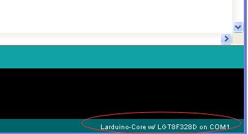
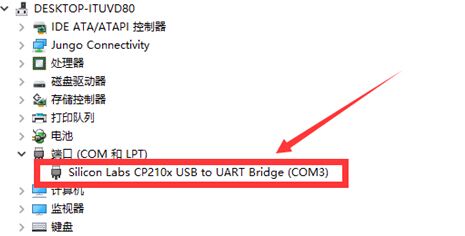
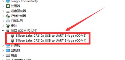
Since there are two USB cable connect to one PC and one Aduino ID there are onething need to be carefull that’s the Serial port,each of time you compile and download the LoRa_Tx and LoRa_Rx You have to choice the correct Serial Port.You can see the serial port on the right down corner which shows as below:
6.) Serial Port Monitor the TX and RX communication.
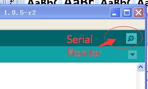
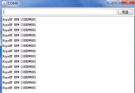
After Compile and download the Software the TX will start the wireless transmission periodically and you can set the Rx serial port and check the received data package by click the “Serial Mornitor”.
It will open a new windows and display the data received.shows as below:
Note: You can check the UART Library which content the function for UART communiction here is the Route: HoepRF-HSP->libraries->HopeRFLib -> HopeDuino_UART.
3.Paremeter Definition and Description.
“LoRa. H” and “LoRa. CPP” library file repository paths in the Arduino IDE folder/libraries/HopeRFLib;
- FreqStruct
Type: Union type
Description: for RFM9X frequency register definition
Content: the Freq, long, 4 bytes, frequency values;
FreqL, bytes, in view of the Freq split the low frequency values of 8 [0:7];
FreqM, bytes, in view of the Freq split the frequency values of 8 [8:15];
FreqH, bytes, in view of the high Freq split frequency values of 8 [16:23];
FreqX, byte, redundancy, rounding 4 bytes, No meaning. - Modulation Type
Type: enum-type
Description: select Modulation and demodulation system
Content: OOK, FSK, GFSK, LORA
OOK: ON-Off – the Key ;
FSK: Frequency – Shift – Key:
GFSK: FSK modulation with gaussian filtering;
LoRa :Semtech characteristic spread spectrum modulation technique. - moduleType
Type: enum-type
Description: select the target module models
Content: LoRa module EVB/DK Kits(RFM92W,RFM95W,RFM96W,RFM98W). - sfType
Type: enum-type
Description: define LoRa mode, spreading factor (SF – spreading factor)
Content: SF6, SF7 SF8 SF9, SF10, SF11, SF12. - Modulation
Type: modulationType type
Description: define modulation demodulation system, OOK, FSK, GFSK,LoRa by selecting one of the them. - COB
Type: moduleType type
Description: definition module model, COB said Chip – On – Borad, can be choice from LoRa module EVB/DK Kits(RFM92W,RFM95W,RFM96W,RFM98W). - Frequency
Type: type lword (unsigned long)
Description: the target operating Frequency, the unit KHz, such as: Frequency = 433920, on behalf of 433.92 MHz. - SymbolTime
Type: type lword (unsigned long)
Description: the target rate, the unit ns, such as: SymbolTime = 416000, representing 416 us each symbol, It means the rate is 2.4 kbps. - Devation
Type: type lword (unsigned long)
Description: the target work frequency deviation, in view of the FSK and GFSK launch needs to be defined, unit KHz, for example: Devation = 45, It means the Frequency Deviation is 45 KHz. - BandWidth
Type: type of word (unsigned int)
Description: the target work receive BandWidth, for receiving need to define the unit KHz, for example: BandWidth = 100, on behalf of the receiving BandWidth is 100 KHz. - OutputPower
Type: unsigned char
Description: the target output power, in view of the need to define the launch, range 2-20, unit dBm, for example, is set to 10 means the Output Power is 10 dBm. - PreambleLength
Type: type of word (unsigned int)
Function: Preamble of packet length setting, need to be configured for launch, byte units. - CrcDisable
Types: bool type
Description: choose whether or not to bring in a packet function CRC, set true representative prohibit CRC function;Set up false open CRC function. - FixedPktLength
Types: bool type
Description: define packet is fixed packet length, or longer packets, set true representative fixed packet length;Set the false on behalf of the variable-length packet format. - SyncLength
Types: Byte type
Description: wireless packet format, the synchronization word length, set the range is 1 ~ 8 bytes;Cannot be set to zero bytes. - SyncWord [8]
Type: an array of bytes
Description: set the packet format, the synchronization word, the content of the need and SyncLength set in accordance with (length). - PayloadLength
Types: Byte type
Description: in fixed packet length model, defining fixed packet length. - SFSel
Type: sfType type
Description: set LoRa mode of spread spectrum factor, can choose SF6, SF7, SF8, SF9, SF10, SF11, SF12 one of them. - BWSel
Type: bwType type
Description: set LoRa mode emission bandwidth parameters, can choose BW62K, BW125K, BW250K, BW500K one of them. - CRSel
Type: crType type
Description: set the CodeRate LoRa mode, can choose CR4_5, CR4_6, CR4_7, CR4_8 one of them. - PayloadLength
Type: Byte type:
Description: in fixed packet length model, defining fixed packet length. - SFSel
Type: sfType type
Description: set LoRa mode of spread spectrum factor, can choose SF6, SF7, SF8, SF9, SF10, SF11, SF12 one of them. - BWSel
Type: bwType type
Description: set LoRa mode emission bandwidth parameters, can choose BW62K, BW125K, BW250K, BW500K one of them. - CRSel
Type: crType type
Description: set the CodeRate LoRa mode, can choose CR4_5, CR4_6, CR4_7, CR4_8 one of them.
4.Function Definition and Description.
- vInitialize
Type:Function
Parameter: none
Return value: none
Description: initialization module (chip), suitable for RFM66 module, the program started calling;Before the call, it is necessary to the foregoing associated variable is set to complete.Initialization function after the configuration (including call vConfig function), that module (chip) for Standby state, namely, not hair, not closed, not sleep. - vConfig
Type: Function
Parameter: none
Return value: none
Description: configuration parameters to the module (chip), applicable to the program need to reconfigure the parameters in the process of work.Also need to complete the associated variable is set before invoking it.If the associated variables set up complete, the follow-up is unchanged, only want to reconfigure a parameters, can be called directly;If need in the process of work, the work of switching frequency, etc., need to modify the relevant parameters, and then in the call.After the call, need to use working mode switching function, so that the chips accurately to the specific work mode, the mode switching function are: vGoRx, vGoStandby, vGoSleep etc. - vGoRx
Type:Function
Parameter: none
Return value: none
Description: configuration module (chip) into the receive mode. - vGoStandby
Type: Function
Parameter: none
Return value: none
Description: configuration module (chip) to enter standby mode. - vGoSleep
Type: Function
Parameter: none
Return value: none
Description: configuration module (chip) into sleep mode. - bSendMessage
Type: function
Parameter: MSG [], unsigned char pointer type, with emission data array called entrance (pointer);Length, unsigned char types, to launch the data length, the unit is byte;
Return Value: returns a bool type, true indicates the successful launch;False indicates failure to launch, such as: push a timeout, and so on and so forth;
Description: the data are sent to launch, just send a (a frame);Sent after the completion of automatic return to Standby mode (Standby mode). - bGetMessage
Type: Function
Parameter: MSG [], unsigned char pointer type, calls for receiving data array entry (pointer);
Return Value: return value is the length of the receiving data, if it returns 0 means no received data;
Description: query whether receives the data, the query object is chip output IO state, if not received data, returns 0;If the received data, returns the length of the received data, after the charge, module (chip) is still in a state of receiving.
5.PIN definition
| RFDuino Board | MCU (Lgt8f328) | RFM9x modules(Or Chipset) |
| 13 | PB5 | SCK |
| 12 | PB4 | MISO |
| 11 | PB3 | MOSI |
| 10 | PB2 | nCS |
| 9 | PB1 | POR |
| 8 | PB0 | DIO0 |
| 7 | PD7 | DIO1(Jumper) |
| 6 | PD6 | DIO2(Jumper) |
| 5 | PD5 | DIO3(Jumper) |
| 4 | PD4 | DIO4(Jumper) |

