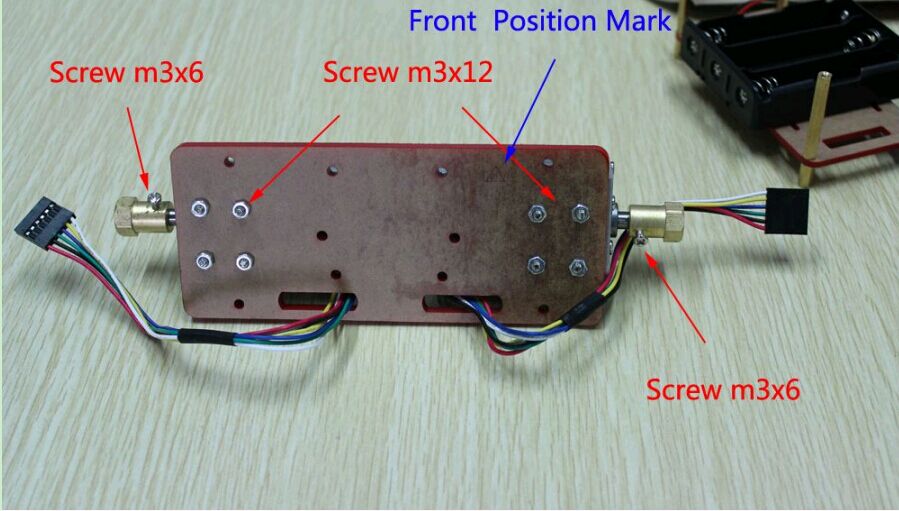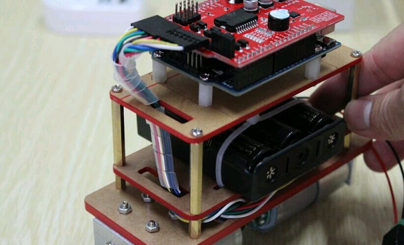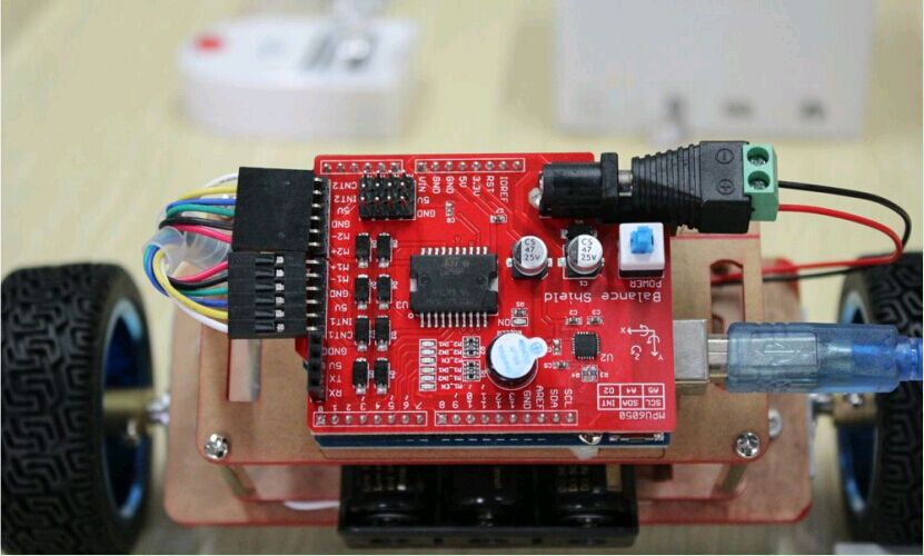
RFduino Board User Manule
RFduino Board which is compatible with Arduino UNO R3 and Arduino IDE. We recommand you use the Source Arduino 1.0.5 as IDE.
RFduino Board which also name HopeDuino But we used to call it as RFduino board.If there are any questions please contact us sales@odlstore.com. We will give more details about the name.
1.Prepare Hardware and software:
- RFduino board
- Arduino IDE 1.0.5 version
- Silabs CP2102 driver package
- HoepRF-HSP hardware and softare service package(Click and download directly)
- USB cable (A mouth turn B)
2.Installation
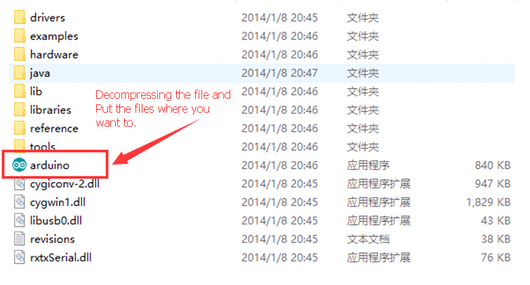
1.) Arduino IDE installation
Download the Arduino 1.0.5 package extract directly to need to put the path, this version is free of installation.As shown in the figure below:
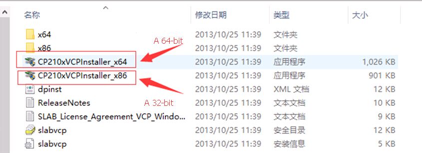
2.) CP2102 chip driver installation
Download “CP210x_VCP_Windows” decompression, in computer system, according to you choose a 64 – bit or 32-bit drivers, double-click the install.As shown in the figure below:
3.) Installation HoepRF-HSP hardware and softare service package(Click and download directly).
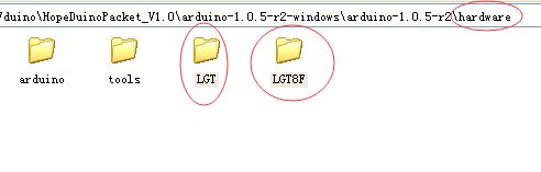
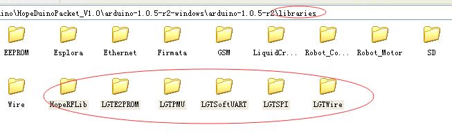
Download the “HoepRF-HSP“hardware and softare service package decompression,you can find two folders “hardware” and “libraries”, Copy the Files under those two folders to the Arduino 1.0.5 “hardware” and “libraries” folders which has the same name.As shown in the figure below:
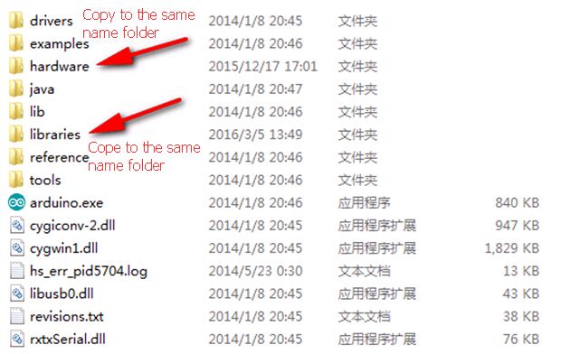
Copy the content of the “hardware” in HoepRF-HSP to the file Arduino 1.0.5 “hardware”.
Copy the content of the “libraries” in HoepRF-HSP to the file Arduino 1.0.5 “libraries”.
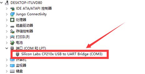
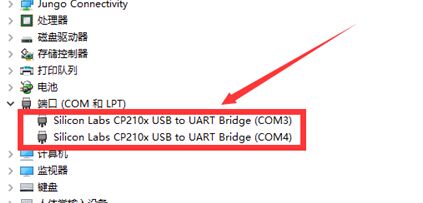
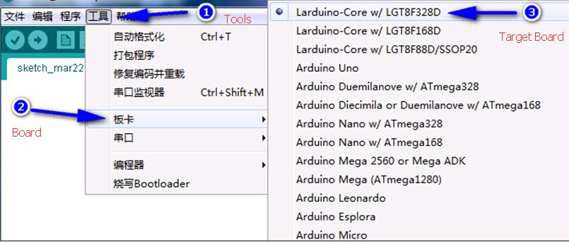
4.) Connect the RFduino board to PC through the serial port.
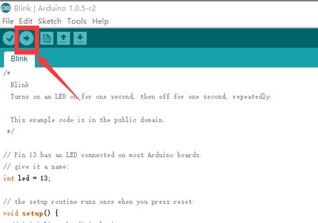
Double-click the arduino. Exe “to open the arduino IDE interface, the interface of select [ToolS] -> [ Board] -> [Larduino core w/LGT8f328d ], as shown in the figure below: