Wireless Module Customization Value-Added Service
Why?
Wireless Communication simply say is the Transmitter Broadcast the electrical signals to space with a radio signal and the Receiver receives the radio signal from space and changes back into electrical signals. The circuit of the wireless communication is critical to some factors, like the power supply, impedance matching(related to the efficiency of Broadcast), the capacity of resisting disturbance, ext. That’s required the Wireless Communication circuit has an independent working environment.That’s why most of the wireless communication unit work as an independent module.That’s our chance.
Purpose
RF Circuit Design requires experience and expensive test equipment, we have both resources and plus the Mature supply chain.most of the wireless module in the market focus on some brands, wireless module customization will bring the benefits of the brand image for our customers, we can name the module which is compatible with the company brand. We can rename the Core chipset which can keep the secret of the solution out of competitors.
Process
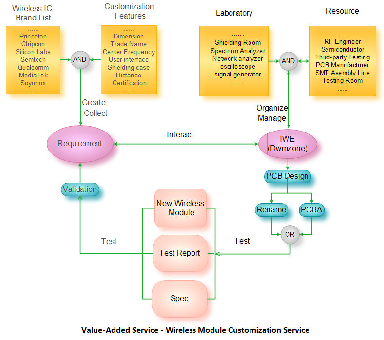
The Basic service for the customization of the wireless module turns the chipset to modules.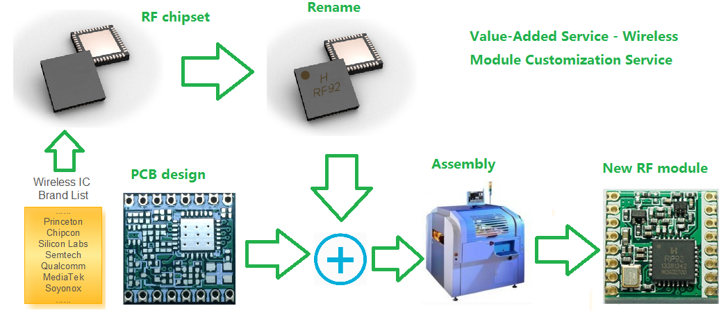
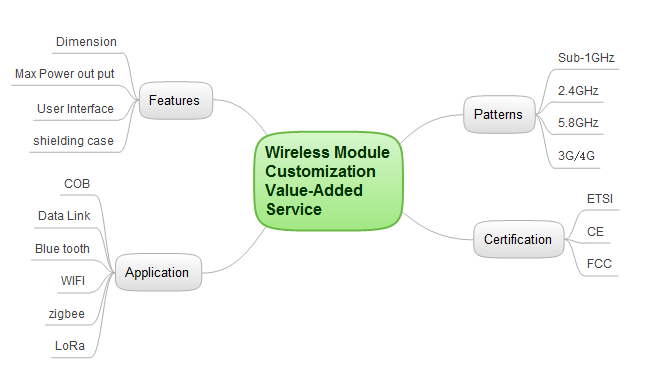
The first customer has to choose a chipset from the Wireless IC brand list, like the Princeton, Chipcon, Silicon Labs, Semtech, Qualcomm, MediaTek, Soyonox, ext. and the features of the wireless module like the Dimension, Trade Name, Center Frequency, User interface, Shielding case, Distance, Certification, ext.
and Formed a requirement document, that means Customer know exactly they want, we only need to input the Experience RF engineer to do the design, test, and manufacture.
Value-Added Service – Wireless Module Customization Service
scope of the business
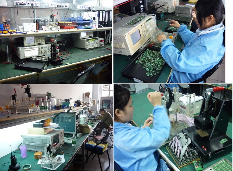
Laboratory
For further information please contact us:
E-mail: sales@odlstore.com Skype: ameisina
Twitter: Dwmzone Facebook: Dwmzone
Youtube: Dwmzone
Website: http://www.odlstore.com